Continue to Site

Welcome to our site!

Electro Tech is an online community (with over 170,000 members) who enjoy talking about and building electronic circuits, projects and gadgets. To participate you need to register. Registration is free. Click here to register now.

  • Welcome to our site! Electro Tech is an online community (with over 170,000 members) who enjoy talking about and building electronic circuits, projects and gadgets. To participate you need to register. Registration is free. Click here to register now.

Low Voltage variable regulation

Status
Not open for further replies.

aroman

New Member
My friend and I have successfully completed the first half of our project to manually control current output of an 85 amp alternator.
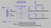
To achieve this we have removed the manufacturers regulator and
supplied current to the field via a voltage controller and a 5k pot plus a couple of resistors (and capacitors etc for noise suppression).
Everything good so far, The system is able to dial in current to the field and we bring the volts up to around 14.4v with the pot.
We would appreciate advice as to how to proceed with the next stage.
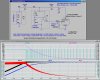
The current generated is used to maintain charge in our boats 12v battery bank. When any drain is put on the bank of course the loss is shown as a drop on the volt meter and vice versa when any appliance is turned off. Is there a way of varying the current supplied to the field to constantly hold the voltage at the original 14.4 volts? We have found that the alternator starts charging at around 2 volts
input to the field and reaches maximum output with 11.5v @ 6 amps
As you can see I have only slight understanding of what we have done as all the design has been done by my mate and I have just
put components together.Would really appreciate any advice as
to how to achieve this self-regulating system if it possible to do
relatively simply.
Thanks Aroman Sailing Vessel "Liana" Cairns Harbour
Australia​
 
A voltage regulator regulates the voltage so that the voltage remains the same when the load current increases.
Your manual field current controller does not regulate the voltage.

The manufacturer's voltage regulator adjusts the voltage so that it is correct for the temperature.
 
Field controller diagram

Thanks Audioguru, I guess the best way to receive the answer is to ask
the right question. I know now what is needed is a field controller,
could anybody post or link to a schematic that would do the job of
controlling the input to the field to match the drain on the main
battery bank when appliances are turned on or off
Thanks Aroman
 
I have the same comment as audioguru. What was wrong with the original Voltage Regulator that came with the alternator? It was designed to accomplish exactly what you are trying to build.

An automotive voltage regulator (either internal or external) looks at the vehicle's system (battery) voltage, compares it to a preset value (typically about 14.4 to 14.8V), and then pulse-width modulates the field current of the alternator so as to get the system bus voltage to the correct value. It is even temperature compensated, so that it automatically adjusts the voltage higher at lower temperatures (to adjust for battery chemistry). Besides, you can go to an auto parts store and buy one for $30
 
Last edited:
MikeMI. You are quite correct about settings for automotive alternator regulators
however when charging battery banks on a vessel we could be talking about 200 to 800 amp hours. When a car starts up the alternator has only to top up a small loss of charge.
When a vessel uses its main propulsion motor to drive an alternator the owner always wants to get the quickest (Read cheapest) safe
charge rate possible.Such marine systems are on the market for many hundreds of dollars. I (as well as a lot of other yachties) do want to find out a circuit diagram to control the field so as to be putting in the maximum safe current.
regards aroman
 
Like they said twice put the factory regulator back in! It will give you all the amps that type of alternator is capable of putting out all ready! And it will then regulate the voltage when the batteries get up to the proper charge.
If you need faster charging speed get a bigger alternator! Physics dictate what the maximum amperage an alternator puts out. No matter what you do there is a limit to what amps you can pull at a specific voltage.
And very few stock alternators can hold the maximum amp draw for more than a few minutes before the diodes and or the windings start to over heat.

There is no free meal with a charging system. If you cheat the voltage regulation system you can make a stock alternator to put out higher voltage but it still has the same or often some what less amp rating. To get the higher voltage you will need to spin it faster in order to get any amps at that higher output voltage. Thats the trade off.
Same with the amp limit. You cant pull more than what the stock alternator is rated for unless you change the windings. (less windings but with heavier wire) But then you will have to speed it up to get the higher amperage out of it while maintaining the correct voltage.

If you need faster charging you need more peak amp capacity, and the easiest, simplest and cheapest way is to just get a bigger alternator.
There is no other simpler way to do it. You can buy high amp alternators that are the same style as the stock ones for far less than you can build one yourself!

I know what you are tying to do and simply put, bigger amp hour capacity batteries require bigger amp output alternators!
 
Thanks tcmtech, Allow me to point out some more specific parameters.
I have swapped alternators from 55amp to 85amp I am not trying to obtain
maximum output, merely UP TO 70% of 85amps for say a initial charge period of an hour. My battery bank (lead acid) totals 3x70amp batteries. Manufacturers regulation points are on at 13.8 off at 14.4. I am not trying to do anything except keep the maximum Safe input charge going in
and not cutting back as I know the settings of the manufacturers regulator does when it senses 14.4 of surface charge. I can do this now manually without overheating either alternator or batteries. I am not trying to reinvent
the wheel just get a diagram of a field controller
 
Here is a Behavioral simulation of a standard alternator charging system. You can quibble about the voltage set points, the battery model (which I had to monkey to get it to simulate in a reasonable time), etc., but this is a good approximation of how it works.

If you study the voltage regulator section, you will get insight into what is in a standard automotive regulator. The snubber diode is internal to most regulators, but has to be there to smooth the alternator field current.The model of both the alternator and Voltage Reg have realistic values.

Note that the field voltage/current starts out full-on. As the battery voltage comes up, it reaches a point at which the VR begins modulating the field excitation by turn the switch on/off. Both the rate as well as the PWM duty-cycle change to adjust the average field excitation to cause the alternator output to reduce as the battery reaches near full charge. In the limit, the field is turned on only for a very small fraction of the cycle. In your example, the system would stay in the mode where the field is on 100% for several hours before begin to taper.

Is your question "Given a particular alternator, how do I redesign the Voltage Regulator so that I can recharge large batteries in as short a time as possible?" If it is, then **broken link removed**. Then come back and let's talk about it.
 

Attachments

  • AlternatorPWM.jpg
    AlternatorPWM.jpg
    422.6 KB · Views: 147
  • AlternatorModel.jpg
    AlternatorModel.jpg
    104.3 KB · Views: 140
Last edited:
I see a potential problem. That is the potential! Err... umm.. the voltage that is.;):D
If your trying to force the batteries to TAKE a higher amp rate charge for any period your alternators voltage output will have to go much higher than the safe limit that the boats electrical system can handle.
You would charge the batteries faster but if your running 18 -20 volts, not unrealistic when force charging a weak battery, into the 12 volt boat electrical equipment lots of smoke and probably some fire is going to come out all over the place. :eek:
Being a prairie dweller I am not all that familiar with a fire on water but I hear its a real problem when the boat sinks in an effort to put itself out! :eek:

YOU might want to talk to Jesus and either have him put in a good word for you or teach you how to walk on water!
If you dont get one you need the other! ;) :)
 
Status
Not open for further replies.

Latest threads

New Articles From Microcontroller Tips

Back
Top