Hello guys.
I frequently use the (probably Chinese made) XH-M609 boards to protect all kinds of batteries (especially 18V Power Toll batteries who serve as a self made bower bank).
These boards work fine for me. I can set cut-off voltage and hysteresis. All great.
The issue I have:
If the board disconnects the power due to low voltage in the battery, the board itself stays powered and will deep discharge the battery if I forget to disconnect the battery in time (days).
My thoughts so far:
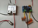
I did get a momentary switch and a SS-Relay (picture attached). With the switch I wanted to enable power to the board for 2-3 seconds, until it checks the Voltage of the battery and could turn on. In case it turns on, I wanted to use the output of the board to feed the input, until battery is low and everything shuts off. To make this happen, I bought a DC SS-Relay (which can handle my source voltage (16-20V).
I however can not manage to wrap my head around the wiring. The issue I have is that the circuit diagram for the relay. It seems to expect the following wiring:
Battery+ -> Load -> SwitchedRelaySide Input [marked +] -> SwitchedRelaySideOutput [marked -] -> Ground. I currently am lost, can't manage to wrap my head around the wiring.
Question1:
What suggestions do you guys have to realize the board totally shuts off in case of low voltage battery?
Question2:
In case you find my approach with the momentary switch and the SS-Relay useful, can you give me some hints in regards to the wiring, please?
Thanks for reading this far")
I frequently use the (probably Chinese made) XH-M609 boards to protect all kinds of batteries (especially 18V Power Toll batteries who serve as a self made bower bank).
These boards work fine for me. I can set cut-off voltage and hysteresis. All great.
The issue I have:
If the board disconnects the power due to low voltage in the battery, the board itself stays powered and will deep discharge the battery if I forget to disconnect the battery in time (days).
My thoughts so far:
I did get a momentary switch and a SS-Relay (picture attached). With the switch I wanted to enable power to the board for 2-3 seconds, until it checks the Voltage of the battery and could turn on. In case it turns on, I wanted to use the output of the board to feed the input, until battery is low and everything shuts off. To make this happen, I bought a DC SS-Relay (which can handle my source voltage (16-20V).
I however can not manage to wrap my head around the wiring. The issue I have is that the circuit diagram for the relay. It seems to expect the following wiring:
Battery+ -> Load -> SwitchedRelaySide Input [marked +] -> SwitchedRelaySideOutput [marked -] -> Ground. I currently am lost, can't manage to wrap my head around the wiring.
Question1:
What suggestions do you guys have to realize the board totally shuts off in case of low voltage battery?
Question2:
In case you find my approach with the momentary switch and the SS-Relay useful, can you give me some hints in regards to the wiring, please?
Thanks for reading this far