Continue to Site

Welcome to our site!

Electro Tech is an online community (with over 170,000 members) who enjoy talking about and building electronic circuits, projects and gadgets. To participate you need to register. Registration is free. Click here to register now.

  • Welcome to our site! Electro Tech is an online community (with over 170,000 members) who enjoy talking about and building electronic circuits, projects and gadgets. To participate you need to register. Registration is free. Click here to register now.

Low side current measurement

Status
Not open for further replies.

gilardino

New Member
i want to use low side current measurement. I connect shunt resistor 1ohm in series with servo. I amplify it using opamp and the output goes to ADC. But during my testing, the ADC reads different2 values although the load is same and the servo is at the same position.

this is my testing. I make my adc read the certain value (x) when the servo reach 90 degree. Then my servo move to 30degree and move back to 90 degree. The value is still x. then it move back to 30 deg and then 90 degree. The value change to y. And when i close the supply. I start from beginning, the value i get can be y value. Why is this happened?

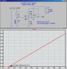
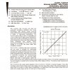
Based on the attachment (page7), i want to make shunt offset adjustment (i make R1, R4, R5 = 1k). I simulate using multisim. I confused with the last equation Vout. It is like not in order and does not include R1. When i simulate in mulsitim, when i change R1, the Vout changes alot. I tried to calculate and it is just can not match the equation. Anyone got any idea about this?

Thanks.
 

Attachments

  • 00894a-current.pdf
    430.8 KB · Views: 833
That is correct, the equation is not including R1, which is in error.
R5 is in effect in parallel with (R1+Rsense).

If indeed Rsense << R1, then its effect is negligible and you can simplify the equation to: R5||R1.

This resultant value, R5||R1 should be substituted in the equation where R5 appears.

In addition, your opamp should be of the rail-to-rail variety.
 
What OpAmp are you using?
 
Most Op-Amps do not work when the inputs get near the power supplies. If your supply is 12 volts then the inputs should be kept in the range of 3 to 10 volts.

A R-R amplifier can work then the inputs are at any voltage from supply(-) to supply (+).

Some amplifiers work form Supply(-) to (supply(+) - 3 volts). That is to say form ground to 3 volts down from the positive supply.
 
Practical circuit
 

Attachments

  • LowSideCurrentMonitor.jpg
    LowSideCurrentMonitor.jpg
    212.4 KB · Views: 534
From the practical circuit, is it does not matter if i do not put R4 and R5 (based on pdf), Since i want to get the constant voltage value? My supply is only 5V.

Can you give example of rail to rail opamp? Which op-amp has rail to rail characteristics?

I tried R1 parallel with R5 and sub to R5. I also can not get the match calculations. is it can not just depend on the multisim result?

Thanks.
 
From the practical circuit, is it does not matter if i do not put R4 and R5 (based on pdf), Since i want to get the constant voltage value? My supply is only 5V.

That means that the LM324 will not work. It is not rail-to-rail. It can only pull up to Vdd-1.5V.

To minimize the need for R4 and R5, I used the 10K (my R4) between the shunt and the non-inverting input. This is so that the non-inverting input sees an input resistance similar to what the inverting input sees; this minimizes offset due to bias currents.

Can you give example of rail to rail opamp? Which op-amp has rail to rail characteristics?

TLC2272 see below: The two things that make it a good choice for your application are:
"@ Output swing includes both supply rails" and
"Common Mode input range includes negative rail"

I tried R1 parallel with R5 and sub to R5. I also can not get the match calculations. is it can not just depend on the multisim result?

Thanks.

I dont use multisim:D

Note
 

Attachments

  • TLC2272.jpg
    TLC2272.jpg
    282.2 KB · Views: 455
Last edited:
Status
Not open for further replies.

Latest threads

New Articles From Microcontroller Tips

Back
Top