Continue to Site

Welcome to our site!

Electro Tech is an online community (with over 170,000 members) who enjoy talking about and building electronic circuits, projects and gadgets. To participate you need to register. Registration is free. Click here to register now.

  • Welcome to our site! Electro Tech is an online community (with over 170,000 members) who enjoy talking about and building electronic circuits, projects and gadgets. To participate you need to register. Registration is free. Click here to register now.

low power switching circuit dc

Status
Not open for further replies.

laverdure

New Member
Hi Guys,
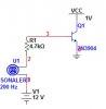
I have a challenge here,,, I have been away from hardware electronics for awhile, now I am in software, I have a old Kenwood car alarm that I wish to use,,,, the siren had 3 leads, one -- ground, 2 -- constant power of 12vdc, and the other 3 -- switching voltage of 0-off, 1.01vdc on…. I somewhat remember doing this in college but how do I make the switching circuit???? Man I feel old :eek: …. Thanks….
 
How about a pull-up resistor to +12V with a normally closed switch to ground. Tie the junction of switch and resistor to the input. Switch closed, alarm off. Switch open, pull-up resistor sources current into the input, pulling it above 1V, alarm makes noise.
 
What about this?

Let me give more background to this challenge. When the alarm is activated there is no voltage at the switching wire, when the alarm is tripped, i.e. open door or another sensor, the voltage at the switching wire is now approximately 1.01vdc ,,, do they make a relay, reed or solid state……anything….. , that will activate at 1vdc ???? :confused:
Thanks
 
This is backwards compared to what you said in your first post. All you need to do is to wire a normally-open switch from the "alarm input" to ground. Closing the switch will make the alarm go off. This could be a switch similar to the one that lights the dome-light in your car.

Do you need to "reverse" the logic so that the application of a positive voltage turns on the alarm? If so, use an NPN transistor like a 2n3904 or 2n2222. Connect emitter to ground. Connect collector to the "alarm input", connect a 4.7K resistor to the base. Applying 3 to 12V to the other end of the base resistor will turn on the alarm.
 
Would the 1vdc from the signal wire turn on the "switch"???
Sorry if I didn't clarify myself on the first post ;)
Thanks
 
Let me give more background to this challenge. When the alarm is activated there is no voltage at the switching wire, when the alarm is tripped, i.e. open door or another sensor, the voltage at the switching wire is now approximately 1.01vdc ,,, do they make a relay, reed or solid state……anything….. , that will activate at 1vdc ???? :confused:
Thanks

Would the 1vdc from the signal wire turn on the "switch"???
Sorry if I didn't clarify myself on the first post ;)
Thanks

No, the switch shorts the "alarm input" to ground if closed. The switch is either totally open (∞Ω), or a short (zeroΩ). A relay contact can do that; so can an NPN transistor or NFet.
 
Like This????
 

Attachments

  • Switch_1.jpg
    Switch_1.jpg
    14.2 KB · Views: 139
Try that one first.

It's much simpler.
 

Attachments

  • ALARM.gif
    ALARM.gif
    5.2 KB · Views: 154
Status
Not open for further replies.

Latest threads

New Articles From Microcontroller Tips

Back
Top