Continue to Site

Welcome to our site!

Electro Tech is an online community (with over 170,000 members) who enjoy talking about and building electronic circuits, projects and gadgets. To participate you need to register. Registration is free. Click here to register now.

  • Welcome to our site! Electro Tech is an online community (with over 170,000 members) who enjoy talking about and building electronic circuits, projects and gadgets. To participate you need to register. Registration is free. Click here to register now.

Low Pass Filter Basics

Status
Not open for further replies.

Suraj143

Active Member
I’m going to feed a square wave signal to a low pass filter (RC filter).What I only know is the cut off frequency.
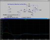
R=10K, C= 10uF
Cut off frequency = 1.59Hz

Let say I’m feeding a 1Khz square wave.
Voltage level 0V-5V
PWM signal from a PIC pin @ 50% duty cycle.

My question is why I have to worry on the PWM frequency?
 
Hi,


It depends on what you want to get at the output. You want a sine wave or a smoother square wave, or perhaps something else like a smooth DC voltage?
What is it that you need at the output?
 
Because the filter amplitude response rolls-off gradually, the closer the PWM frequency is to the cut-off frequency of the filter, the greater the amount of ripple there will be at the output of the filter. The ripple amplitude will diminish at a rate of 6dB/octave above the cut-off frequency.
 
Last edited:
Hi this is what I want.I want a smooth DC output to feed to LM317 ADJ pin to control voltage by varying PWM input given.

My only doubt is what is the relationship between cut off frequency (1.59Hz) & the PWM frequency (1Khz)....?

Why cant I give some other PWM frequency like 50Hz, 600Hz etc....?
 
Hello again,

Ok so you are interested in the DC smoothing.

The relationship between the cutoff frequency of the filter (f) and the PWM frequency (F) and the ripple amplitude is roughly:
Ampl=f/sqrt(F^2+f^2)

so as F is increased the ripple goes down, but as f is increased the ripple goes up. So you want low f and high F.
Because F is usually a lot higher than f, as f goes up the ripple goes up approximately proportional to f, and as F goes down the ripple follows approximately inversely proportional to F so you dont want to decrease F if you dont have to.
A side effect of low f however is slow response to changes in the PWM duty cycle which adjusts the nominal DC output level.
 
Last edited:
Here is a your filter with 50% duty cycle pwm inputs of 1000, 500, 100, and 50 Hz. Which would you like to control your LM317.
 

Attachments

  • D25.jpg
    D25.jpg
    285.3 KB · Views: 186
Look how much less ripple a two-pole active filter has compared to your simple RC filter.
 

Attachments

  • D27.jpg
    D27.jpg
    309.7 KB · Views: 181
Hello again,


For a passive two pole filter with the same cutoff for both sections but the impedance of the second stage 10 times the first, the approximate relationship is:
Ampl=f^2/sqrt(F^4+2.41*f^2*F^2+f^4)

So now the change in ripple is proportional (or inversely proportional) to the square of the frequencies instead of before with just being proportional (or inversely) to the frequencies with only one stage.
 
As MikeMl has shown, simulation is a very powerful tool to perform "what if" scenarios, and decide for the optimal one, depending on your requirements.

Mike...I have a question for you: What is the Spice directive .ic V(a)=2.51 V(b)=2.51 doing? I assume it is setting an initial node bias, correct?
 
When doing a Transient (.TRAN time domain) simulation, all Spice variants perform an Initial Conditions DC solution to establish where all nodes in the circuit sit at time=0. In the sim above, the stimulus is a square wave, which takes on only two values, 0V or 5V. At Time=0, the input Pulse Voltage source has a value of 0V, so the Initial DC solution causes all nodes in the filter to settle to near ground.

The duty cycle of the Pulse source is 50%, so the average DC level is near 2.5V. Now it takes a 2Hz filter several seconds to settle to the final value when the input steps from 0V to an average value of 2.5V. To avoid showing the startup transient, and waiting for thousands of cycles of the 1000Hz PWM input, waiting for the filter output to settle, knowing that the expected level is tending toward 2.5V, it is easier to just force the internal nodes in the filter to an initial condition of 2.5V before allowing the simulation to run. That way, it is easier to plot and show the ripple component riding on the dc level...
 
Last edited:
Indeed Mike, I'm very familiar with the long settling times it takes on long-time-constant circuits.

Thanks for the advice, now I've another tool when I'm doing simulations.
 
Ok guys thanks for the support.

Now I understood somewhat better. :) For me no need to think deeply on the cut off frequency, just concentrate on R & C values that they will give you minimum ripple along with a good response time :)
 
Status
Not open for further replies.

Latest threads

New Articles From Microcontroller Tips

Back
Top