Continue to Site

Welcome to our site!

Electro Tech is an online community (with over 170,000 members) who enjoy talking about and building electronic circuits, projects and gadgets. To participate you need to register. Registration is free. Click here to register now.

  • Welcome to our site! Electro Tech is an online community (with over 170,000 members) who enjoy talking about and building electronic circuits, projects and gadgets. To participate you need to register. Registration is free. Click here to register now.

Low Frecuency Audio Detection

Status
Not open for further replies.

Menticol

Active Member
Hello!

This is a revisted version of my previous, improperly made question.
It would be great if the moderator (please) delete the previous one, I had provided the link to avoid littering.


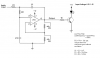
My goal is to drive a load when the bass of an audio signal reaches certain threshold. To do that, I have modified an existing circuit.

I know 741 is an old lousy IC, but such simple task is an alternative to the trash bin. Filter works great, bass sounds awaful, but at least corresponds to the frecuencies (and the peaks) that I need. By the way, gain is still very low. I have to set the volume of my test amplifier all the way up, to hear the beats of the 741.

The problem is, the transistor doesn't respond. I've adjusted the resistors for maximum gain as possible without oscilation, but either stays on or off all the time. Only when The 741 starts oscilating violently the light of the LED corresponds with the machine-gun like sound.

Any advice would be great!
 

Attachments

  • filtro.PNG
    filtro.PNG
    73.8 KB · Views: 1,331
Last edited:
The +input of the opamp must be biased at 0V from the input.
The opamp must have a gain of 1.6 to be a Butterworth filter and will oscillate if the gain is more than 3.0.

The input signal level must be pretty high to trigger the transistor since the audio gain is low.

The LED will probably quickly burn out since nothing limits its current.

The circuit should have a peak detector so that the LED lights long enough to be seen.
 
Thank you by your reply, Audiogru

As far as my empirical knowedge goes, I tried to improve the circuit to meet your suggestions.

a) I don't know how to bias the 741, maybe shunting the input via a resistor with the ground?

b) If I remeber correctly (if not sorry), on another thread you told me that the negative voltage necessary for Pin 4 could be "emulated" shunting it with two 1M resistors, one to +Vcc other to GND.

Is that applicable to the 741?

Avoiding negative voltages and batteries in series would be great for my device.

Thank you again
 

Attachments

  • PAN.PNG
    PAN.PNG
    88.1 KB · Views: 474
Last edited:
The 741 opamp needs to have its input biased. Your circuit has it floating without a DC voltage. It should be biased at 0V (connected by the speaker) for a dual-polarity supply or at half the supply voltage for it to use only a positive supply. The audio amplifier already has its output (before the output coupling capacitor) at half the supply voltage.

The resistor values can be 10 times higher then the filter capacitors can be accurate 100nF 5% film type and the input bias resistors can also be 10 times higher.
I selected gain resistors so that the filter is a Butterworth type.

The LEDs will look fairly dim because the circuit feeds the LM3915 with half-wave input signals that light the LEDs for only half the time. If you use one of the Peak detector circuits shown in the datasheet of the LM3915 then the LEDs will light continuously during sounds and look much brighter. Also, momentary sounds will light the LEDs long enough to be seen.

The 12V supply voltage is too high for the LEDs which causes the LM3915 to get hot when all the LEDs are lighted. Add a single power resistor between the +12V and all the LEDs with a filter capacitor as shown in the datasheet. The power resistor and the LM3915 will share the heat.
 

Attachments

  • LM3915 with bass filter.PNG
    LM3915 with bass filter.PNG
    44.3 KB · Views: 1,906
Last edited:
Status
Not open for further replies.

Latest threads

New Articles From Microcontroller Tips

Back
Top