Continue to Site

Welcome to our site!

Electro Tech is an online community (with over 170,000 members) who enjoy talking about and building electronic circuits, projects and gadgets. To participate you need to register. Registration is free. Click here to register now.

  • Welcome to our site! Electro Tech is an online community (with over 170,000 members) who enjoy talking about and building electronic circuits, projects and gadgets. To participate you need to register. Registration is free. Click here to register now.

Low current power supply from stored current.

Status
Not open for further replies.

McGuinn

New Member
Sorry if the topic is confusing... What I am looking for is some advice on the construction of a power supply for a small transmitter.

I have a radio transmitter which is designed to to sit on a device which has a duty cycle of ~1%, so can sit unused for a period of time. It's switch controlled, and I need to send a radio signal from this device when it gets pressed used.
The design constraint is that the device may only be on for second of two, and I want to be able to pull enough power from the device to transmit for 3 seconds. This means having to store energy in a capacitor (I can't use a battery due to space constraints) and have it discharge over the period of 3 seconds.

The transmitter is ~4mA when on. The device has a power supply of 6V AC, which I will rectify to get 9.1V DC. I then need to smooth this and use a voltage regulator to bring it down to 5v DC (+/- 5%). That's no problem, all that works...

The problem is that I need to be able to supply this 5V for 3 seconds, and not have it drop off in a gradual slope, I need definate ON/OFF switching. With the present circuit, I get a wave while the capacitor discharges...
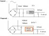
The circuit goes:
AC -> Bridge Rectifier -> Smoothing Cap 22uF -> Storage Cap 1000uF -> 5V Regulator -> Smoothing Cap .01uF -> Transmitter.

Can you recommend any way of inproving this to eliminate the gradual dropoff?

Sorry if it's complex. I will get around to doing a circuit/drawing soon...
 
Have you measured the performance of the circuit as you've written it?, the 1000uF should store a reasonable amount of energy - if it's not enough, fit a bigger capacitor, also use a low drop out (LDO) 5V regulator, then the voltage on the capacitor can drop lower before the output starts to drop.
 
Hi McGuinn

at 4mA i think you will need a starting voltage a bit
higher than the 9v you are using.

Also you will of course want an 'efficient' conversion
from the stored voltage to the 5v feed for the small
transmitter.

Here is a small switching circuit that gives a 5 volt
controlled output from a fairly wide supply range of
input voltage, so that as it falls, the 5 volt should
remain until the input falls below 8 volts.

Unlike a straightforward regulator, this circuit does
not act like a dropper resistor and waste power, the
designer claims efficiences better than 88 per cent.

It might be worth a look.

**broken link removed**

* 80% efficiency (from 30mA to 90mA out)
* very tiny Rf inductor
* very cheap circuit (under 50 cents in parts!)
* good 5v regulation
* input: 8v to 20v?
* output: 5v @ 150mA maximum

I would also suggest rewiring your rectifier circuit
to give around 18 volts which would mean it holds more
energy, and hopefully lasts a little longer.

Best of luck with it, John :)
 

Attachments

  • Possible_arrangement.jpg
    Possible_arrangement.jpg
    16 KB · Views: 439
Hi, John

i've made some corrections on Your sematic...
 

Attachments

  • rect.jpg
    352.8 KB · Views: 453
Thank you sebi !

But what did you think of that little regulator ?

John :)
 
John, Sebi, Nigel

Thanks for taking the time to think about this.
I am restricted to 9.1VAC as this is what the rectfied 6VAC gives.
I see what you are saying, increase the voltage and you increase the potential stored in the cap... But that's not a runner.

I ran a mockup on bread-board, and using a PP3 battery and the cap where it is on your circuit above, I got a discharge of ~2 seconds. This goes along the lines of what I expected from the maths I used.
When I moved the cap to the other side of the regulator, I got ~1 second... My mistake... I understand the reason fully now.
So, I need to add a ~500uF cap, and use an LDO regulator... I haven't seen these in Maplin, are they stocked? (Nigel may know? Suspect you're from the UK Nigel?? ;-) )

Just a question on the more efficient circuit... does this method not provide less efficiency as only one of the lines is recified? Or is it that the AC wave is offset by 180 degrees so remains efficient???

I should have paid attention in college! ;-)

Thanks Guys!
 
Hi McGuinn,

Thanks for looking at my suggestion,
however,
you have muddled up a couple of little bits.

The extra efficiency i suggested is from using a type
of regulator that does not waste power.
Did you check out that page i gave ?
**broken link removed**
Most regulators do not act like that.

And you are correct that when rectifying and smoothing
the 6volt ac you get 9.1 volts.
However,
you can also rectify it and smooth it the other way
round, and get a negative 9.1 volts.

If you arrange that the two 9.1 volts are added,
then this uses exactly the same ac supply,
but gives almost double the voltage out.

The AC supply can do this without any change.

You can use the same AC supply to give 9.1v or @ 18v
simply by altering the rectifying arrangement.

Doing this will not require the AC supply to be
altered or changed in any way.

A higher voltage will hold more potential power and
in conjunction with a higher efficiency regulator
may give you the three seconds you need.

It may even give you some extra time using a standard
regulator unit.

Using larger capacitors will help with the supply at
9.1 volts, but the rate of voltage drop will soon
bring it down below the regulators range, by
increasing the voltage applied to the regulator you
will improve matters, if you also increase the caps
you might get it to give three seconds simply by
using the doubler as shown and bigger caps with the
regulator you are using now.

I hope my attempts at an explanation can be
understood, its not easy trying to explain the
actions of electronic circuitry.

Best of luck with it, John :)
 
McGuinn said:
So, I need to add a ~500uF cap, and use an LDO regulator... I haven't seen these in Maplin, are they stocked? (Nigel may know? Suspect you're from the UK Nigel?? ;-) )

There's a clue in my location - England :lol:

Maplin stock an LM2940CT-50, order code AV22Y, according to my catalogue - it has a drop out voltage of only 0.5V, a 7805 is 2V.
 
Guys, thanks again. I didn't see the England bit in your user details Nigel, I was rushing, but tomorrow I will sit down and apply myself to this fully.

I'll be back with a more structured set of questions soon! :)
 
My opinion: use a voltage doubler rectifier and a small buck regulator e.g. LM 2594. I'm sure with two 1000uF cap. enough for 4sec.
 
John,
I have had a good read of the SMPS page, and my feelings are that this method, while efficient, is going to be difficult to support for the following reasons:
It uses switching technology I am not yet 100% familiar with yet.
It increases the component count, and may exceed my space limitation.
There is insufficient information about the input voltage range.
Finally, I don't see enough information about device protection.

In saying that, I intend on looking at it as a possible solution in future projects!
I will evaluate using the voltage doubling you mentioned earlier, but I think I see a chink in the armour with that one... If I double the voltage from 9.1 VDC to 18.2 VDC, the dissipation of heat from the 7805 will increase (I think it's proportional), possibly negating the benefit! But, I will not dismiss this, I will test it soon.

Nigel,
I am looking at the LDO reg. from Maplin, this would be more efficient than the 7805 alright.

Sebi,
I have just downloaded the datasheet for the LM2594, I will look at this instead of the other SMPS circuit. Lots of maths in the datasheet though, and I don't have an oscilloscope yet!

Thanks again guys!
 
McGuinn said:
Nigel,
I am looking at the LDO reg. from Maplin, this would be more efficient than the 7805 alright.

I don't know as 'efficient' is quite the right word, but it will function on a lower input voltage before the output starts to drop.
 
Don't worry about maths, just use the application example.
On NSC homepage You can make on-line design,but this cct. will work.
 

Attachments

  • 2594.GIF
    2594.GIF
    6.7 KB · Views: 339
Status
Not open for further replies.

Latest threads

New Articles From Microcontroller Tips

Back
Top