Continue to Site

Welcome to our site!

Electro Tech is an online community (with over 170,000 members) who enjoy talking about and building electronic circuits, projects and gadgets. To participate you need to register. Registration is free. Click here to register now.

  • Welcome to our site! Electro Tech is an online community (with over 170,000 members) who enjoy talking about and building electronic circuits, projects and gadgets. To participate you need to register. Registration is free. Click here to register now.

looking for servo controller circuit diagram using switch ?

Status
Not open for further replies.
nigel.
yes I think microcontroller will makes me busy and time consuming for me to learn. since I'm no good at electronic.

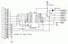
the 555 site you give me, I can't read the left side words, 0-10 volt input ??

like I said before, it's very hard for me to understand the english word specially adding two pods and switch between them, it's alot easier for me if you draw it.

I don;t mind try it/build it if it's works.
question how can I change/trim the position of the servo if I need more say 10 degree more or less ?

regards
ruddy
 
oh it says I can trim the position and center, I did not read well.

btw I don;t need the center.

if you draw it for me I will do like you said, building this 555 project is not difficult for me as long as the circuite diagram is easy to understand for a guy like me.

rud
 
Nigel said use a toggle switch.It's NOT a push button.If it's okay for you of course it will be good.No flip-flops will be needed to remember the state.

Sorry,I thought the base board was all you need to build an interface for yourself.Unfortunately there's another AVR there with confidential code.It sucks!This guys sells interface to make money.

I'm searching for an STK300 compatible programmer which is really easy for you to build.Only a few resistors and a 74LS244 is needed.AVR Studio will support it.
 
It's here,the circuit is as below,really easy to DIY.

The latest AVR Sudio doesn't support it.You need Code Vision AVR or ICCAVR.I have the CVAVR setup and crack files(1.8MB),as well as the ICCAVR setup and crack files(11MB).If you decide to build the STK300 yourself.I can send you the installers via Email.Neither of them has ATtiny15L in its support list,but they support tiny13.It's a headache.You need a new HEX for them.I can write the C project for you.Anyway it's getting complicated.You better try the 555 toggle solution first.If it works,forget the AVR.If you're not saticfied with it,come back here.
 

Attachments

  • stk300.gif
    stk300.gif
    6.7 KB · Views: 999
ok, I agree with alex.
i'll try the 555 first but that schematic needs flipflop and push botton switch somewhere which I have no idea where to put it.

I heard that 556 is already have the "flipflop"

regards
rud
 
calico said:
ok, I agree with alex.
i'll try the 555 first but that schematic needs flipflop and push botton switch somewhere which I have no idea where to put it.

I heard that 556 is already have the "flipflop"

regards
rud

First suggestion is try to forget about the push button.If with a toggle switch you can still fullfill your mission,you can avoid a lot of problems.Just follow Nigel's link.

If you insiste on that push button.Try CD4013 D type flip-flop,download its datasheet for the pin map and search for typical applications based on it.
 
alex,
yes I insist of using 1 push botton switch.

let me search "your instruction", i'll get back 2 u.

regards
ruddy
 
I'm not good at analog electronics.So I can't tell you what to do with the circuit.It looks applicable.You need to figure a way to feed the output of the flip-flop into a 555 circuit.Seek help on this issue from others in this forum,sorry.
 
How about something like this. Only 1½ ICs 2 capacitors, 5 resistors and 2 diodes.

The values of r1c2 and r3c1 would be chosen to give 20mS.
The value of r2c2 would be chosen to give a closed pulse.
The value of r4c1 would be chosen to give a open pulse.

r2 and r4 should really be variable.

As a starting point for the values, I'd try,
C1,C2 = 1uF
R1,R3 = 37k
R2,R4 = 5k preset variable.

Mike.
Edit - added guessed values!
 
Last edited:
calico said:
are you sure this drawing works ??

I haven't built it but it should work. Anyone else see anything wrong with it?

It could be improved by adding a capacitor and resistor to the set or reset inputs of the flip flop to make it power up in a known state.

Mike.
 
if you think it will work, I'll start soldering it by tomorrow.
could you please re send the drawing in higher resolution ?

regards
ruddy
 
While I believe that this circuit will work, I am not confident about my initial guesses at the RC values. If this guy is going to build this and he does not have access to an oscilloscope, it would be nice if someone with the abilities to put this into a simulator could come up with a better guess on the RC values.

For anyone with access to a good simulation package, I believe the parameters for the 4093 gate are:

Assuming 6V power supply
Hysteresis level 1V
Input level for low output level 3.5V
Input level for high output level 2.5V

If nobody answers, I'll dig my old text books out and, work out some better values tomorrow.

Mike.
 
Mike,
you said simulator, is it a software simulator you talking about ?

if it's can you name the best simulator programs ?

regards
ruddy
 
Which bit doesn't work?

Things to check.
IC2,
Pin 5 should be low (0v) and go high (6v) when the push button is pressed.
Pin 1 should toggle when ever the push button is pressed.
Pin 2 should be the opposite of pin 1.

When pin 1 is high, this enables the oscillator built around IC1A to run.
Do you have access to a scope so you can tell if this is running.
Another way to tell if its running is to remove R2 and check the voltage on pin 3 of IC1. It should be around 3V.

As I said above, the values for the resistors are a guess. They are a starting point. The output from the 2 oscillators should be a short pulse every 20mS. The 20mS time base is set by the value of R1 (and R3) and the pulse length by R2 (and R4). For your application, I would guess that the top oscillator should have a pulse around 1mS and the bottom one 2mS.

Mike.
 
Status
Not open for further replies.

New Articles From Microcontroller Tips

Back
Top