Continue to Site

Welcome to our site!

Electro Tech is an online community (with over 170,000 members) who enjoy talking about and building electronic circuits, projects and gadgets. To participate you need to register. Registration is free. Click here to register now.

  • Welcome to our site! Electro Tech is an online community (with over 170,000 members) who enjoy talking about and building electronic circuits, projects and gadgets. To participate you need to register. Registration is free. Click here to register now.

Looking for a car battery charger circuit

Status
Not open for further replies.

avz

Member
Hi
I'm looking for a proven and reliable circuit diagram of a car (lead acid 12V - not hybrid) battery charger. preferably, one that stops/shut down when the battery is fully charged.
Thanx.
 
The simplest circuits I have seen use a Op-Amp comparator circuit and a 555 timer IC.

The concept is the Op-Amp is set up to read the battery voltage and once it sees the correct voltage enable the 555 timer to do few minutes more charge time before deactivating the battery charger power.

By adding a bit af hysteresis to the Op-Amp the circuit can be made to automatically start charging again once the battery voltage goes low enough as well.
 
Do you want a high-current charger that recharges a completely discharged starting battery in a few hours, or do you want a low-current maintainer that keeps a little-driven vehicle from self-discharging or overcomes the parasitic drain due to the car's always-on load?

The maintainer type will also recharge a badly discharged battery, but it might take two to three days.

The high current charger requires a big transformer, while the maintainer can be powered from a cheap wall-wart.
 
Hi
Thanx for your replies. can I ask that you will post/send the circuit diagrams of them? MikeMl - I think that the maintainer will do.
 
Hi
Thanx for your replies. can I ask that you will post/send the circuit diagrams of them? MikeMl - I think that the maintainer will do.

The key to this project is starting with the correct Wall-Wart Plug-in Power Supply. Do you have one that might be suitable?

Ideally, you should find an older-style, real iron-copper (heavy) transformer-based (as opposed to a lightweight switching-mode converter). It should put out about 15Vdc (unregulated, but has rectifiers built-in) at about 1A (14VA or 14Watts). The input side should match your Wall Plug AC Voltage.

One that puts out ~14Vac (not internally rectified) will work too, but we will have to add a full-wave bridge rectifier to the circuit.

You didn't put in a country when you registered for the web site, so I do know how to help you obtain the Wall-Wart. Hereabouts, there are literally hundreds of these available at the local thrift shops and they are cheap (one fifth of the price of a cup of coffee at Starbucks).

What you are looking for is like the Hammond BPD2EE. This one is available new, (look at the data sheet) but I would be looking for one from a surplus store or a thrift shop.

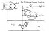
I have several versions of the circuit to go between the transformer and the battery, but the final details are dependent on the transformer you start with. Give me an idea of what you can find as the transformer, and I will customize the circuit when you tell me what you can find...
 
Last edited:
works great built one been in use 30 years.
it slowly discharges the battery slowly thru the 1k and 10k resistors though when the power is off.
I put a small relay in series with the amp meter to stop that.
 

Attachments

  • Heathkit_GP-21_BatteryCharger.jpg
    Heathkit_GP-21_BatteryCharger.jpg
    44.9 KB · Views: 151
MikeMl - thanx for the detailed response. I have a few wall dc adapters (as well as transformers), among them one that provides several voltage outputs at a current of 1A, so I guess that it meets the demand.
 
Ideally, you should find an older-style, real iron-copper (heavy) transformer-based (as opposed to a lightweight switching-mode converter).
So what do you have against switching adapters?
 
So what do you have against switching adapters?
I am a Ham Radio Operator, therefore I hate the @#$%#$ things because of the RFI that they generate. I take them out in the back yard and use them for target practice. No LED lights, No CFLs, No solid-state ballasts, and I replace all of the cell phone and other chargers with adapters which use real iron transformers. Switchers are not allowed on my property...

For the charger, we need the intrinsic current limiting built-into the Wall-Wart Transformer.
 
Did you read the data sheet I linked? Air gap in the magnetic path?
No, I had not.
But here's an explanation for one type of current limiting transformer.
It uses a magnetic shunt between the primary and secondary.
 
AFAIK, all of Wall-Warts are intrinsically safe (short-circuit protected). Some are fused (usually self-resetting). Avoid those for battery charging.

The ideal one for the battery charger is the kind that is not fused, but is intrinsically current limited by design. This allows the charger to recharge a battery that was totally discharged (like forgetting to turn off the headlights) without overheating.

I will be posting the schematic for the charger as soon as I find it...;)
 
Status
Not open for further replies.

Latest threads

New Articles From Microcontroller Tips

Back
Top