Most people I know have gone to electronic versions, however. Here are some references:
**broken link removed**
**broken link removed**
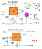
I have attached an image of the Guelph schematic. The Welwyn schematic is pdf and too big, but I have attached the explanation that downloads with it. It is really quite simple. You just set up your flip-flops to determine whether the pulse is longer or shorter than what you set the switch point to be.
Remember, the receiver does all of the decoding. If you have an oscilloscope, it is kind of fun to circuit trace the signals and see what the composite looks like when you wiggle the sticks. I have done that to show mixing to other fliers. Where the servos plug in, however, it is simply a single channel of PWM.
There is a variety of commercial switches made and many of the hobby sites have them. John
Oh, and thanks.

 ) and it never flew again...
")

 , but it works great.