Continue to Site

Welcome to our site!

Electro Tech is an online community (with over 170,000 members) who enjoy talking about and building electronic circuits, projects and gadgets. To participate you need to register. Registration is free. Click here to register now.

  • Welcome to our site! Electro Tech is an online community (with over 170,000 members) who enjoy talking about and building electronic circuits, projects and gadgets. To participate you need to register. Registration is free. Click here to register now.

Logic probe design

Status
Not open for further replies.

throbscottle

Well-Known Member
First off, all this only exists in LTSpice. It doesn't really exist yet.

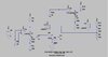
I came up with a design for a logic probe which gives pulse stretching on the high or low indicator, by connecting 2 o/c comparators as wired OR to each indicator. One of the comparators is connected as a monostable to do the pulse stretching. So either one dominates.

What I really like is that the pulse stretching comparator, on it's own, gives a slow flashing indication when the input is a high frequency, like the old HP 545A does from back in the 70's. I think it's a really good clear indication, unlike a lot of other designs on-line which fudge around this.

Of course it all goes wrong when the outputs are connected together, the nice slow flash gets chopped to pieces, and the choppy signal interferes with the monostable.

Any suggestions?
 

Attachments

  • spice.jpg
    spice.jpg
    82.4 KB · Views: 231
No input, no output, signal paths in all possible directions, a line drawn through the middle of a component . . . There is no way to figure out what the circuit actually does, or is supposed to do.

ak
 
Don't connect the outputs together!

I use a seven segment display in my home made logic probes. The three horizontal bars for high, open, low and the vertical bars at one side for high & low pulse.
 
The "probe tip" is the signal source in the middle.

Sorry it's not very clear, trying to do this through a fuzz of TV being on and being very tired.

The two comparators on the left are for the high level indication. I seem to have got the high and low references mixed up although it doesn't matter as there are no invalid inputs in this test.

The two on the right are for the low level indication. The 3 20k resistors provide reference points, the outputs are active low. Each pair of comparators would drive their own LED.

So each of the plain boring comparators will give a correct (active low) high or low indication. Each of the monostables will give a pulse when a pulse is input, and if a signal such as a clock pulse is applied it will trigger slowly between high and low states, which I really like.

Connect the outputs together and I get a long pulse out for a short pulse in, or the output will show whatever level is going in. Exactly what you want from a logic probe. This part of it is fine and happy and appears to work ok. Very conveniently the monostables don't even need the input terminal changing for correct leading edge because the normal comparator sets it up to be in the right state to start with.

The problem occurs when the input is a clock signal because the normal comparator is switching away happily, making a complete mess of the slow pulses from the connected monostable. It seems I would have to add a lot to it to stop this from happening, simple R's, C's and D's aren't giving useful results...
 
HAH!
Instead of trying to have a pulse stretcher and a plain comparator wire ORed together, I put them in sequence.
Fiddling around with it for a while gives a high or low normal indication for normal signals, or a stretched indication for pulses. A pulse train with short enough pulses close enough together will cause both lights to flash simultaneously due to a cunningly placed sync capacitor.
Feeling pleased.
I'll draw a diagram of acceptable standard now... Though I might put a line through a component just to annoy AK.
 
Ok diagram of the new version. C4 is to sync the high and low LEDs if a clock faster than about 10Hz so they flash together instead of alternately. I put in the "no stretch" switch to disable pulse stretching if required as it gets messy around the 10Hz area.
The probe will also indicate slow changing signals by bursts of synced activity in between the normal high and low changes.
Some logic probes have a memory function so they remember 1 state change. It was good enough for HP in 1976, so I might see if I can do it too.
Still needs some tweaking. Still only exists in LTSpice - reality may be different. It is relying on some very low level signals!
ZD1 is 2.4v. I forgot to put it on.
 

Attachments

  • Schematic_Design__logic-probe.sch_inux-generated_files.pdf
    22.7 KB · Views: 178
This might be of interest, a single mixed signal chip, PSOC. This
might be a candidate to consider.

It has onboard Vref, OpAmps that can double as comparators, PGA,
SC/CT blocks that can also be used as comparators, DACs to gen
bias V, pulse stretcher, LED/LCD drive, and a whole lot more.

The DACs can be set under program control or thru logic control of
their DAC buss, logic to do so onchip.

This is a rough workup, some things not yet connected, of what
would be used. You darg and drop components onto canvas, config,
and use a wire tool to perform internal wiring and wiring out to pins.

Tool is PSOC Creator, it and compiler free. Board I think would be the
$ 15 board would suffice.

1623027669698.png


There is an arm processor in it as well if you want to do some advanced
features.

Attached is a catalog of chip components. In PSOC land a component is an onchip
resource.

Regards, Dana.
 

Attachments

  • Component List (2).pdf
    183 KB · Views: 184
A good logic probe will respond tp pulse signals in the sub microsecond and preferably down to tens of nanoseconds range.

As well as cost and size, how fast is the logic in the PSoC system?
 
That is waaaayyy overkill for al logic probe, which can be made with as little as just 2 transistors. Besides, I already have all the parts to build this or a dozen others which are already published on the web.
I did think about trying to use an old smoke alarm chip, but I was already down the route of modifying an existing design by then...
I might still try that just for kicks :)
 
The comparators are good for 110 nS with 50 mV overdrive.

Logic is ~ 15 nS, like gates, LUTs (if using registered version 33 Mhz),
counters (32 bit 30 Mhz, 8 bit 67 Mhz).......

Yes it is overkill unless advanced PCB size possibly at issue due to
reduction in needed component count. Or features not normally
found in legacy probes.....display voltage, RMS, more advanced
display info, more analog f()'s....


Regards, Dana.
 
Last edited:
But then it's not a logic probe. It becomes a multi-purpose tester.
The HP 545 which is my source of inspiration has a bandwidth of 40MHz. I don't know how many comparator nano-seconds that translates to, but it is faster. They used a peak detector to get more speed out of the "slow comparators" (their wording) they had. Copying the design as well as I could with limited info into LTSpice makes a big improvement where it starts to taper off. Clever folks.
My PCB for the first iteration of this (which was actually a probe designed by someone else I was just going to build, but then started tinkering with it) measures 0.5" by 4" (101.6 x 12.7mm). It would have been 3.5" long but I had to fit a dpdt switch on for that design. Didn't seem any point making it smaller.
(EDIT) I have a couple of board-edge-switch sliders saved from broken toys so I might try using those, for this one.
 
Last edited:
Status
Not open for further replies.

Latest threads

New Articles From Microcontroller Tips

Back
Top