Continue to Site

Welcome to our site!

Electro Tech is an online community (with over 170,000 members) who enjoy talking about and building electronic circuits, projects and gadgets. To participate you need to register. Registration is free. Click here to register now.

  • Welcome to our site! Electro Tech is an online community (with over 170,000 members) who enjoy talking about and building electronic circuits, projects and gadgets. To participate you need to register. Registration is free. Click here to register now.

LM555 circuit noise filters

Status
Not open for further replies.

cdr

New Member
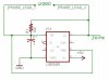
I am using an LM555 timer to generate an alternating voltage signal through an RC circuit. The circuit is used to measure resistance/conductance of liquids. My problem is that the circuit picks up a lot of noice from the overhead flourecent lighting and other stuff. Can someone suggest where to to put some capacitors to filter the noise?

This is the same problem I was having with my pH probe circuit which is now fixed.

Ron H., maybe you can run another simulation for me?

thanks

Go
 

Attachments

  • lm555.jpg
    lm555.jpg
    25.1 KB · Views: 777
1. Tie pin 4 (reset) to VCC.
2. Add 100nF from pin 5 to GND.
3. Add power supply decoupling as suggested by JFDuval.

For the resistor, 100 ohms is already too low a value. If you are expecting liquid resistance in that range, I doubt that you will get good results with this circuit.
 
Thanks, the circuit is working much better now.

Ron H, can you give me some guidence on how the resitor value effects the results of the liquid conductivity measurement. I do not fully understand the relationship between the resitor value and conductivity accuracy. I changed the resistor to 330K but I do not understand what effect it had on the circuit? In other words, I'm confussed and frazzled.

thanks again.

go
 
cdr said:
Thanks, the circuit is working much better now.

Ron H, can you give me some guidence on how the resitor value effects the results of the liquid conductivity measurement. I do not fully understand the relationship between the resitor value and conductivity accuracy. I changed the resistor to 330K but I do not understand what effect it had on the circuit? In other words, I'm confussed and frazzled.

thanks again.

go
The frequency of oscillation is determined by the feedback resistor in series with the 555 output resistance (in your circuit). The output resistance is probably in the tens of ohms range, and will vary depending on the type of 555 (bipolar or CMOS), the manufacturer, the supply voltage, temperature, and from unit to unit. If you keep the feedback resistor above some arbitrary value (depending on your requirements), say 1kohm, then the output resistance will be more or less insignificant. If you liquid has low resistance, then the output resistance may dominate your oscillation frequency, which will cause reduced sensitivity and possibly erratic readings.
If your liquid resistance is high, then this is all irrelevant. If not...

Are you planning to calculate the resistance with an equation, or create a lookup table using known resistance values, or... ?
 
I have an equation to calculate the liquid conductivity based on the 555 oscillation and a temperture factor. The probe will primarily be used to measure conductivity of fresh water and saltwater solutions. I can take some measurements and get a general idea of the resistance of both.

If I understand correctly, I need to set my feedback resistor (the 100 ohm in the circuit of the first posting) above the output resistance of the 555 (in the 10's of ohms range), but below the resitance range of the liquids I am measuring?

go
 
Well, I suppose you've realized that 10k - 200k is an easy range to handle. Are you going to measure conductance? Frequency will be inversely proportional to resistance, so you would have to calculate a reciprocal to get resistance (unless you can measure oscillator period). I'm not a microcontroller expert (are you using one?), so that seems like it would be difficult. Nigel probably has a reciprocal routine.

It would seem to be easier to not have a feedback resistor. Does your system require oscillation in the absence of a resistor (liquid)?

A CMOS 555 will give you more consistent results, because its output swings from rail to rail, which is not true for the bipolar version (LM555, etc.).
 
I am using a microcontroller, PIC 16F877. I connect the output of the 555 to an input pin on the PIC and count the frequency of the 555. Then I use my equation to calculate the conductance based on the 555 frequency.

I'll get a CMOS 555 and see if I get better results, with or without the feedback resistor. And no, I do not need osillation in the absence of liquid.
 
cdr said:
I am using a microcontroller, PIC 16F877. I connect the output of the 555 to an input pin on the PIC and count the frequency of the 555. Then I use my equation to calculate the conductance based on the 555 frequency.

As you are using a PIC16F877 you have analogue inputs, you could use one of those to measure the resistance directly!. A simple opamp could be used to convert to a suitable level.
 
You are right, I guess I could just use the analog input to measure the resistance. The only reason I use the 555 is to generate the osillating signal to prevent oxidation on the probe tips (as would accure with a staight DC voltage).

Can you suggest a better way to ge the same results using the functinality of the PIC and opamp?

go
 
cdr said:
You are right, I guess I could just use the analog input to measure the resistance. The only reason I use the 555 is to generate the osillating signal to prevent oxidation on the probe tips (as would accure with a staight DC voltage).

Can you suggest a better way to ge the same results using the functinality of the PIC and opamp?

go
That sounds like a valid reason. Conductance should be a linear function of frequency, so conversion should be simple.
 
Now I have all kinds of problems, when I put the conductivity probe in the tank it has a different reading then when it is in the same solution but outside the tank. Also, it seem sto be affecting the pH probe reading as well.

Any suggestions?

go
 
Status
Not open for further replies.

Latest threads

New Articles From Microcontroller Tips

Back
Top