Continue to Site

Welcome to our site!

Electro Tech is an online community (with over 170,000 members) who enjoy talking about and building electronic circuits, projects and gadgets. To participate you need to register. Registration is free. Click here to register now.

  • Welcome to our site! Electro Tech is an online community (with over 170,000 members) who enjoy talking about and building electronic circuits, projects and gadgets. To participate you need to register. Registration is free. Click here to register now.

lm3914 fuel gauge (help)

Status
Not open for further replies.
hi again
i change my mind and i want to make the fuel gauge more accurate, crutschow can you help me on this.
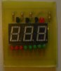
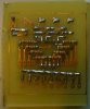
Here is some photos from my project if the speedo and fuel gauge on the same PCB. now i need to make the other part off the fuel gauge.
 

Attachments

  • fuel and speedo front.JPG
    fuel and speedo front.JPG
    51.2 KB · Views: 273
  • fuel and speedo back.JPG
    fuel and speedo back.JPG
    87.7 KB · Views: 238
I don't understand what help you need?
 
I don't understand what help you need?
if you can help me to make solve the problem of the readout voltage that you mention on post 17, here 100 ohms (1/2 tank) i have 3.5V and not 3V. hi have try to make your circuit but i cant make it to go to the right values, and i put diode and the resistor on mine circuit but always if the same result.
 
Okay. So did you build the circuit with the same components and values as my simulation in Post #9?
 
The LM324 is basically the quad version of the LM358 so there should be no difference in the simulation unless the models are somehow significantly different.

Post your simulation showing where it is not working.
 
Last edited:
What is your +V voltage? Which regulator are you using? My LTS sim, using LM317, gives +V = 5.2V (which is too low for the LM358/LM324)
 
yes i have lm317 that is giving 5.2v, what is the v+ recommended to lm358?
I had some mistakes on the fist circuit the r1 was wrong and the +v was mising on Bar/dot.
This is my last results
 

Attachments

  • fuel test2.JPG
    fuel test2.JPG
    137.3 KB · Views: 185
The LM358 supply voltage should be at least 2V greater than the voltage you want at the output. I thought you were going to use 8V originally?
The bar/dot input of the LM3914 can be left floating for bar mode. N.b. bar mode consumes much more current than dot mode so you need to ensure the chip max dissipation is not exceeded (I haven't checked whether this is the case in your circuit).
 
Alec you are correct in the maximum voltage output of the LM324/358 versus the supply voltage. Below is the circuit with a 6V output from the regulator which avoids that problem, since the maximum output is about 4V.

The maximum power dissipation of the LM3914 in the circuit is 411mW which is comfortably below it maximum rating of 1365mW.

Gas Gauge.gif
 
Last edited:
I think this will work ok i will build the prototype and make some test, and will post results about-ed.
I will need more help soon on another project that is making my head crazy, is about PC CAR that i will have timer to turn on the computer 30 seconds after having switched on ignition, that is easy using a 555 timer, my problem is turning off the pc only 30 seconds before i turn off the ignition and switch power off, but i will open another thread to it.
tanks crutschow and Alec for the help.
 
just a quick question. Is possible substitute the lm317 to a lm7806 is not because i don't have the lm317 is just because i need to make the circuit small as possible and take out two resisters will help a little.
 
Yes the 7806 should work fine as a replacement.
 
Status
Not open for further replies.

Latest threads

New Articles From Microcontroller Tips

Back
Top