Continue to Site

Welcome to our site!

Electro Tech is an online community (with over 170,000 members) who enjoy talking about and building electronic circuits, projects and gadgets. To participate you need to register. Registration is free. Click here to register now.

  • Welcome to our site! Electro Tech is an online community (with over 170,000 members) who enjoy talking about and building electronic circuits, projects and gadgets. To participate you need to register. Registration is free. Click here to register now.

LM3914 battery checker question

Status
Not open for further replies.

GregE

New Member
Hi all! I've been working on a battery checker circuit using the LM3914 LED driver and an HSPD4832 bar graph to create a battery checker for two 9V batteries in series for an 18V top end range. Initially, I wanted to monitor a 16V to 18V range on the bar graph and put together the first circuit below (18 to 16V schematic.jpg). The voltage divider created by R1 and R2 (10k and 17k respectively) should cut the 18V to 11.25V and the 16V to 10V, giving the desired 1.25V range to compare to the internal voltage source. I breadboarded this with a 17V signal and got the expected voltages: 10.72V going into pin 5 out of the voltage divider, 1.25V across R3, and 9.86V as the offset across R4. The bar graph worked perfectly and everything looked good.

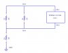
I then realized that I could extend the useful battery range for the circuit this will be driving down to 13V, so redesigned the battery tester to measure from 18V down to 13V (18 to 13V schematic.jpg). With R1 still at 10k, this changed R2 to 3.3k to give a range from 4.47V when driven by 18V to 3.22V when driven by 13V. Similarly, R3 stayed at 12k and R4 was changed to 12k to give a voltage offset of about 3.2V. When the 17V signal was fed into this circuit, I still got the right amount of voltage into pin 5 (4.46V), but the voltage drop across R4 to give the base offset was 7.91V instead of 3.2V and only the first (lowest voltage) LED of the bar graph lit up. I can't understand why the voltage drop across R4 is so large and it's driving me nuts! What am I missing? I'm new at this, so don't rule out a really stupid mistake! Thanks for any advice!
 

Attachments

  • 18 to 16V schematic.jpg
    18 to 16V schematic.jpg
    82.8 KB · Views: 247
  • 18 to 13V schematic.jpg
    18 to 13V schematic.jpg
    83.4 KB · Views: 214
:confused:I'm a bit rusty on LM3914 calcs but I don't see how you get 9.86V across R4 in the first circuit and 7.91V in the second. By my reckoning it should be 1.25 x 36k/12k = 3.75V in the first and 1.25 x 12k/12k = 1.25 in the second.
 
I'm using the current to do the calculations. Current going through R3 should be the internal voltage (1.25V) divided by the effective resistance to pin 8 which includes R3 in parallel with the internal resistance of the chip given as 12k by the spec sheets. This would be calculated as 1.25 X (1/R3 + 1/12000) giving about .2 mA. The current through R4 is then the .2 mA plus the leakage current out of pin 8 given in the specs as about .075 mA, so a total of .275 mA through R4. To figure my resistance for R4, I take the desired voltage offset in the first circuit (10V) and divide by the current to get a little over 36k. For the second circuit, the desired voltage offset is 3.22V and gives the R4 of a little under 12k.
The voltages posted were the ones measured from the breadboard and I can't figure out how I'm getting the 7.91V either, though the 9.86V makes sense.
 
the internal resistance of the chip given as 12k by the spec sheets.
:confused: In the National Semiconductor datasheet I'm looking at the 12k relates to the resistor ladder between pins 4 and 6. I can't find any reference to the input impedance at pin 8; only the pin 8 output current of 75μA (typical, but max = 120μA).
I hadn't allowed for the pin 8 current in my calcs, but as it's an output current I don't see it flowing through R3; only R4. So taking it as 120μA we get R3 current = 1.25/12k = 0.104mA, R4 current = 0.104+0.12 = 0.224mA, R4 voltage drop = 36k x 0.224 = 8.01V.......not a million miles from your measured 7.91V :)
I'm surprised you have such a high value for R3: it will give a LED current of only ~1.2mA.
 
Last edited:
I have an electrical tire inflator that has a red LED display. The LEDs are so dim (maybe only 1mA like in this circuit) that you cannot see them in daylight.
 
Ah, but think of the benefit to the environment AG. Less global warming than if you were running the LEDs at a whopping 2mA :D
 
Thanks for all you help on this alec! I like the idea of brightening up the LEDs. They seem OK indoors right now, but may be too dim when I get them in other environments. I've pushed it to the low end mainly to preserve battery power for the rest of the circuit that I'll be trying to power later.
Now, as to the new information you provided, my understanding is that since pin 7 is directly connected to pin 6 (high end of the internal ladder) and pin 8 is connected directly to pin 4 (low end of the ladder) that the simplified circuit would look something like the one below. This would put the resistor ladder in parallel with R3. Secondly, in the calculation you provided, you used the R4 of the first working circuit (36k) which did indeed give a higher voltage drop near to what I wanted for that circuit, but when you put in the R4 for the second circuit (12k) you get 12k X 0.224 = 2.68V, a far cry from the 7.91V measured. So I'm still stumped! :p
 

Attachments

  • subcircuit.jpg
    subcircuit.jpg
    30.5 KB · Views: 175
Great tool, Eric! Will definitely come in handy. Unfortunately, it only allows the low end of the resistor ladder to be 0V, since pin 4 is hardwired to the 0 rail. My issue is getting the offset of the low end to the correct voltage so that it indicates when the batteries are drained to a non-useful state rather than all the way to zero.
 
when you put in the R4 for the second circuit (12k) you get 12k X 0.224 = 2.68V, a far cry from the 7.91V measured.
Better than my calc! I was confusing the two circuits. And you're right about the ladder being in parallel with R3 in your setup. The spec does allow for the ladder being as low as 8k. If we plug in that value the effective resistance across the 1.25 ref is 12*8/(12+8)k = 4k8, giving a ref load current of 1.25/4k8 = 0.26mA (and a LED current of ~2.6mA). So the worst case current through R4 would be 0.26 + 0.12 = 0.38mA, giving a drop of 4.56V across it. Still some way off your 7.91 :(. Odd indeed. It's possible you have an out-of-spec IC. Was it from a reputable source?

Edit: One thing about your circuits; you have ground at the mid-point of the battery instead of at the lowest point. Could that be a factor?
 
Great tool, Eric! Will definitely come in handy. Unfortunately, it only allows the low end of the resistor ladder to be 0V, since pin 4 is hardwired to the 0 rail. My issue is getting the offset of the low end to the correct voltage so that it indicates when the batteries are drained to a non-useful state rather than all the way to zero.

hi greg,
I will look into changing the Rlo pin #4 as a variable voltage input, on the LM3914 Tool.

E.
 
Success! Thanks to your suggestions, alec, I swapped out the LM3914 chip, but it still didn't work. I then looked at the grounding as you suggested, and lo and behold, I didn't have pin 2 going to the -V as shown in the schematic, but rather to ground. I don't know why this had the effect it did, but when I fixed it, the circuit worked as designed, lighting up correctly and giving me the desired 3.22V across R4! Thanks so much for all your suggestions!
 
Good to know it's now sorted :)
 
Status
Not open for further replies.

Latest threads

New Articles From Microcontroller Tips

Back
Top