Continue to Site

Welcome to our site!

Electro Tech is an online community (with over 170,000 members) who enjoy talking about and building electronic circuits, projects and gadgets. To participate you need to register. Registration is free. Click here to register now.

  • Welcome to our site! Electro Tech is an online community (with over 170,000 members) who enjoy talking about and building electronic circuits, projects and gadgets. To participate you need to register. Registration is free. Click here to register now.

lm35dz circuit - pls comment

Status
Not open for further replies.

alamy

New Member
Hi..

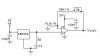
I need your help ..pls put comment on my circuit..

this circuit use temperature sensor...lm35dz....0.01v/*C...
i'm amplify the output ....to get 0.1V/*C...

meaning that , if my Vo = 2.5 V => 25*C...

but the problem is...i have to retuned the my potentiometer to get accurate each time power supplied...

how should i do to improve my circuit in term of stability...any suggestion..

pls advice..

thanks
 

Attachments

  • lm35.jpg
    lm35.jpg
    26.1 KB · Views: 749
I am not familiar with that particular temperature sensor, but the circuit looks fine and should be stable. However most temperature sensors do require about one minute to stabalize, Before you reset it.

Also, do you have any 1 uF Tantalums as Bypass Caps on the 5 volt supplies, going to ground? That would be a Good Idea.

Take care..........Gary
 
According to the datasheet, the LM35 takes up to 4 minutes to stabilize in still air.
I don't know why you have all those op amps. You don't have to use all of the op amps in the package just because they are there. More op amps will cause more drift and error. You also don't need R1 and R2. They have their own drift, and they cause you to have to raise the gain, which also causes more drift and error.
With a 5 volt supply, the LM324 is only guaranteed to reach 3.3v maximum on the output . Is 33 degrees an adequate high limit for your circuit? If not, choose an op amp whose input range includes GND (as does the LM324), and whose output range is rail-to-rail.
You also don't need R3 and C1 unless you are driving a large capacitive load as would be the case if your LM35 is remotely located (which I realize may be the case).
I've posted a simplified schematic below. Note the 100nF decoupling caps added to the ICs' power pins. This helps prevent oscillations that might otherwise occur. I've also reduced your gain control range, which will make the circuit much less sensitive to drift in the potentiometer.
 

Attachments

  • lm35_amp1.jpg
    lm35_amp1.jpg
    9.7 KB · Views: 672
Status
Not open for further replies.

Latest threads

New Articles From Microcontroller Tips

Back
Top