But now from here how do I get it to show me when it switches on and off?
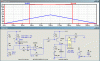
I can measure voltages etc and they show on the graph but can I get a meter circuit so I can attach a meter at various points and watch the voltage change as I change values?
hi.
Measuring voltages:
Run the simulation.
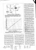
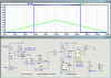
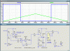
Select V1 and comp for plotting, you should get the plots I have posted.
Place the cross hairs cursor close to where the V1 and comp plot lines cross.
Press and hold down the left mouse key, use the dotted box to enclose the intersection of the plot lines and then release the mouse button.
[do this for the left hand crossing point]
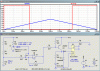
The plot window will be magnified.
Right mouse click the V[n002] label located just above the graph, this will display the 'Expression Editor' window.
Click the 'Attached Cursor' drop down box [ initially shows 'none']
Left click the 1st option, then OK.
This will display a small window, showing the values at the '1st' cursor location.
If you move the cross hair cursor over the plot a large '1' will appear when you are over the '1st' curosr.
Press and hold down the left mouse button and 'drag' the '1st' cursor over the intersection of the two plot lines.
The display window will show the precise values at the 1st cursor location.
If you just want to check without doing the above procedure, then placing the cross hair cursor at the plot line cross over and look at the bottom left of the LTSpice window you will see the cross hair coodinates displayed.
Hope you follow that.
")
BTW: I cannot download your asc file.???
EDIT: after a couple of tries, got the download.