Continue to Site

Welcome to our site!

Electro Tech is an online community (with over 170,000 members) who enjoy talking about and building electronic circuits, projects and gadgets. To participate you need to register. Registration is free. Click here to register now.

  • Welcome to our site! Electro Tech is an online community (with over 170,000 members) who enjoy talking about and building electronic circuits, projects and gadgets. To participate you need to register. Registration is free. Click here to register now.

LM324 Power Supply

Status
Not open for further replies.

123mmm

Member
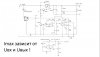
Hello, I built the attached schematic.
I found that the minimum output current is not 0mA.
Using the 300R resistor (Imin), the minimum output current is about 170mA. I replaced this resistor with a 10R resistor and I found that the minimum output current is about 1.7mA.
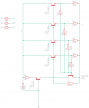
In the place of 2SC5200 and BD140, I used 4 NPN transistors with emitter resistor driven by a BD244.

It is safe to use 10R resistor instead of 330R resistor ?
 

Attachments

  • lm324 russian.jpg
    lm324 russian.jpg
    53.4 KB · Views: 231
  • npn_prot.png
    npn_prot.png
    13.5 KB · Views: 164
Last edited:
When you say that the minimum output current is 170 mA, I assume that you mean that the minimum regulated output current is 170 mA? Some regulators have a minimum output current, below which the output voltage will become too large. Looking at your circuit, I don't think that is the case with your circuit.

It's perfectly safe to use a 10 Ohm resistor.

The only problem is that the minimum regulated current will depend on the exact characteristics of the 5 kOhm potentiometer. The end resistance of the potentiometer could make a significant different to the minimum current setting.

https://www.farnell.com/datasheets/...2.1176877257.1556918111-1491156693.1549152031

That range of potentiometers has an end resistance that is 2 Ohms max, so that is 20% of the 10 Ohm fixed resistor, so there minimum regulated current could vary by 20% between different potentiometers.

On the unmodified circuit, the voltage feedback has an extremely high gain, which is good for keeping the voltage constant as the load changes, but it could lead to instability. Although the op-amp has the high frequency gain limited, from the output of the op-amp to the final output there are three cascaded transistors, so the gain there is huge, and may well vary a lot depending on the exact component values.

The emitter resistors in your modification will limit the gain, and they reduce the chance of particularly high-gain transistors causing instability.
 
The output of the 7812 is the system voltage reference; not great, but ok. The 82K, 5K pot, and 300 ohm resistor for the current limit voltage divider. With Ohm's Law you can calculate the voltage drop across the 300 ohm resistor. That value equates to the minimum output current that the circuit will allow when the current limit pot is set to its minimum position.

Translates - how? Like this. All of the output current goes through the 0.2 ohm current sense resistor, and the voltage across this resistor goes to the current limit amplifier inverting input. When this voltage exceeds the voltage from the pot at the non-inverting input, the amplifier leaps into action and reduces the drive voltage to the power transistors. When the pot is at the bottom of its range, the Imin resistor sets the minimum output current. Because the LM324 input stage common mode voltage range extends below its negative rail voltage, you probably can reduce the Imin resistor to 0 ohms.

ak
 
I checked the power supply for oscillations using the attached schematic for generating a square wave signal. I used as a load a 4.7R resistor rated at 5W.
I used 1N4007 instead of HER508, and I used 3v3 zener diode instead of 13V zeneer diode. The resistor Imin, was modified from 300R to 10R and the Umax resistor was modified to 12K. The transformer is rated at 24Vac and 160VA. The bridge rectifier is 35A/1000V, the filter capacitor is 2x6800uF/80V.
I used a fast constant current for protecting the power transistors if a short circuit happens on the output, until the slow constant current activates: npn_prot.png
On pin 3 of 555, the waveform looks like:DS0000.jpg
On the output of the power supply, the waveform looks like:DS0001.jpg
The PSU tester schematic is: psu_shorter_schematic.png
The tests were made at 10V output voltage.

Please have a look at the waveform from the 2 screenshots and tell me if the output of the power supply oscillates ?
 
Last edited:
There is one thing, the current sense resistor also monitors some of the current used by the supplies circuitry, lowering it right down may trigger current limit without a load connected.
That might not be an issue you'd have to try it.
 
Status
Not open for further replies.

Latest threads

New Articles From Microcontroller Tips

Back
Top