Continue to Site

Welcome to our site!

Electro Tech is an online community (with over 170,000 members) who enjoy talking about and building electronic circuits, projects and gadgets. To participate you need to register. Registration is free. Click here to register now.

  • Welcome to our site! Electro Tech is an online community (with over 170,000 members) who enjoy talking about and building electronic circuits, projects and gadgets. To participate you need to register. Registration is free. Click here to register now.

LM317 & LDR Question

Status
Not open for further replies.

AllanEuerby

New Member
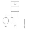
I want to auto. dim a 7-segment display from an LM317 regulator via a light dependant resistor.
The display needs a maximum of 2V (daylight), minimum of about 1V(dark).
The LDR has resistances of about 600Kohm (bright light) to 400ohm (dark).
I don't want to use a 7-segment driver.
I've tried a few resistor combinations, but seem to be missing something...
Any ideas?
Allan.
 
Several things come to mind. One is that the lower limit of the 317 is listed as 1.25 volts. Another is that you'll need to be working at the very bottom end of the LDR range. How much current/power can your LDR handle?
 
LDR is apparently capable of 50mW (Nippon ceramic, Cadmium Sulphide).
Spec says 10Lux=50-100Kohm; Dark=5Mohm, whatever that means.
Multimeter says: 600k to 400ohm (dark to light).
Therefore if 'R1'=LDR & 'R2'=220ohm, Vout should be 1.27 to 1.96V, from
1.25x(1+R2/R1))+R2x0.0001 - 0.0001 being max. Iadj...
Unfortunately, my multimeter disagreed.
Allan.
 
The problem might be your meter. I've run into the same problem.

Plain old resistors don't seem to mind a moderate amount of current being passed thru them during a measurement and the measurement yeilds an accurate value. I've found that thermistors don't like to see the amount of current that a DVM uses for measuring resistance - LDRs might be similar.

I'd measure the resistance another way. Apply a low voltage source to the LDR and another resistor then measure the voltage drops across them- then do the math to back your way into the resistance of the LDR. Choose a value of resistor that yeilds a tiny flow of current. I don't know if this will work but it's what I'd try.
 
AllanEuerby said:
LDR is apparently capable of 50mW (Nippon ceramic, Cadmium Sulphide).
Spec says 10Lux=50-100Kohm; Dark=5Mohm, whatever that means.
Multimeter says: 600k to 400ohm (dark to light).
Therefore if 'R1'=LDR & 'R2'=220ohm, Vout should be 1.27 to 1.96V, from
1.25x(1+R2/R1))+R2x0.0001 - 0.0001 being max. Iadj...
Unfortunately, my multimeter disagreed.
Allan.

I don't know where you obtained the formula "1.25x(1+R2/R1))+R2x0.0001" I assume that R1 and R2 form a voltage divider. If this is the case, then v = 1.25 x R2 / (R1 + R2) assuming that R2 is at the bottom and that the supply voltage is 1.25V.

If you post your circuit we may be able to offer more informed assistance.

You also said "Dark=5Mohm, whatever that means" This means that the LDR has a resistance of 5 M when it is in total darkness.

Len
 
Len,
I understand the Dark=5Mohm - it's the bit about 10Lux that means nothing to me!
In the picture, the round thing is the LDR, the TO-220 thing is the LM317T & the rectangle is R1, middle leg goes to the 7-segment display, right leg +ve.
With R1 at 20ohm & a 10ohm in parallel with the LDR, I can get the output in the right area (about 1.5V), but obviously with 10ohm in parallel with the LDR, variablility is practically nill.
Allan.
 

Attachments

  • 317Circuit.jpg
    317Circuit.jpg
    6.3 KB · Views: 707
Lux is a measure of light intensity - lumens/square meter. To simply say light or dark is insufficient for this situation. It would be safe to assume "dark" means dark enough for you to think there is no light.
 
Allan,
Something like this would be a better option

Len
 

Attachments

  • Light_detector.gif
    Light_detector.gif
    2.4 KB · Views: 700
I wanted to use the LM317 with the LDR to adjust the brightness 'steplessly' - not have two brigtnesses & a switchover threshhold, but thanks anyway.
I'd already thought of the 555 route, but an LM317 & one, maybe two resistors takes up less space than a 555, resistor & capacitor.
 
What you need then is an op amp in lieu of the voltage comparitor.

Move the 100k resistor from the + to the - input and change some resistor values and the output will be proportional to the light input.

The LM317 is not really suited to this purpose

Len
 
Len,

This sounds interesting, any chance of a (simple) circuit & a suggested op amp?
I'm sure you've gathered, that if it's not plain to see on a datasheet, I'm stuck!
Thanks.
Allan.
 
Status
Not open for further replies.

Latest threads

New Articles From Microcontroller Tips

Back
Top