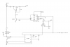
You don't understand transistors. The 5V spec is for maximum reverse base-emitter voltage. The forward drop of a BJT is ≈0.7V, so the Darlington Vbe is about 1.4V. I assumed the Darlington needs Ib>(Ic/1000). The 4.7k between base and emitter has about (1.4V/4.7k)=300uA. The 4.7k resistor between the PNP base and the 2N5551 collector forces about ((60V-1.4V)/4.7k)-300uA=12.2mA Darlington PNP base current. The base current of the 2N5551 is about (5V-0.7V)/4.7k=900uA.
The 4.7k from base to emitter of the PNP Darlington helps speed up turnoff of the Darlington, and shunts any collector-base leakage to +60V, to ensure that it stays off when it is supposed to be off, even if it gets hot.
OK guys, but don't forget I squared R... your 4.7K base resistor will dissipate about 3/4W, so you'll need a 2 or 3W resistor there, unless you can gaurantee a duty cycle of less than 8% (1/12th). Remember, automotive applications are at elevated temperatures so we have to derate. Use 1/2watt resistor for 1/4 watt application...etc...
Also, diode D2 does absolutely nothing for you except dissipate power. You already have a pn junction pointed in that direction, one you're turning on and off. Are you expecting the 12V to go higher than 60? Because that's the only thing in the world D2 would be for...
Also, on your darlington base current calculation, you forgot to subtract another .7v, the collector sat. voltage on the NPN you're using to turn the darlington on... it's 60v - 1.4v (darlington) - 0.7v (NPN) = 57.9V divided by 4700 then minus 300uA.
The purpose of the zener is to protect the darlington driving the Injector. When that device turns off, it's collector will go to twice the VCC (24V if 12, 120V if 60... see LM1949 data sheet Figure 2 page 7 Q1 collector voltage... they show it going up to VZ... the zener clamping voltage) by the nature of inductors. Therefore, the zener should be selected to be less than the max collector to emitter voltage of the darlington. If the transistor you select has one built in, then you don't need it. If you connect it to 60V, you'd be using it as a flyback diode, and you'd need one to 12 also, but you can't if you want that point at 60v so more properly it would be placed across the injector (on the injector side of the fuse, even). It's purpose is to help the field collapse when the injector current is turned off it can no longer flow from Vcc to ground, so it now still flows out from the injector bottom, through the diode (now forward biased since the collector is at 2 x Vcc), back into the top of the inductor to let the field collapse and ease the voltage seen on the collector of the driving device. Remember, current can't change instantaneously in an inductor, so when you turn off the switch, it still needs to flow somewhere...
By connecting the diode to 60v and with the upper darlington turned off, the diode becomes a clamp that will clamp the collector to 60v (not let it go above 60.7V) but does nothing to help collapse the field, and protects a device with a collector to emitter breakdown greater than 60V.
Mike