Continue to Site

Welcome to our site!

Electro Tech is an online community (with over 170,000 members) who enjoy talking about and building electronic circuits, projects and gadgets. To participate you need to register. Registration is free. Click here to register now.

  • Welcome to our site! Electro Tech is an online community (with over 170,000 members) who enjoy talking about and building electronic circuits, projects and gadgets. To participate you need to register. Registration is free. Click here to register now.

Lissajous figure for phase shifter

Status
Not open for further replies.

dr.power

Member
Hello there.

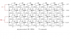
Can you guys please guide me how to connect the pins of my 2 channeled scope to the below circuit so that see the Lissajous figure of the below pic which is a 90 degrees phase shifting circuit?
For instance how to connect 2 channels of the scope so that see the 90 degrees out of phase? (I get confused when thinking about how to connect the reference or ground pins of my scope to the said circuit so that I see a circle on X-Y mode...)

Is the reference point the 0 degrees phase of the phase shifter, and where I should connect the reference pin (i.e the ground pin) of my scope to it?

Thank
 

Attachments

  • fig4.gif
    fig4.gif
    8.6 KB · Views: 369
I am not seeing the attachment?

However if you want to see a Lissajous pattern on a scope you can setup one signal on the vertical channel and if the scope allows the other as an external horizontal input. Another option if the time base allows is to set the time base to X,Y mode where one vertical channel is the X axis and the other is the Y axis. This assumes both signals have the same common.

Hope that helps....
Ron
 
Last edited:
Another option if the time base allows is to set the time base to X,Y mode where one vertical channel is the X axis and the other is the Y axis. This assumes both signals have the same common.
Ron

Ron, What do you mean by that? In scops as I know the ground is common for both channels, It is true for mine of course. My scope has an X-Y mode which when I click on its button I can see the Lissajous figure of both channels when the one signal is connected to the channel one of the scope and the other signal or the phase differentiated signal is connected to the channel 2 of the scope, However regarding the above circuit I got confused about the reference point for the common ground of the scope...

I just have at least 3 wires for scope, A common ground and 2 other pins which are for both channels, Now I do not know where to connect the common ground of the scope in the above circuit so that see the 90 degrees phase shift between the outputs of the circuit?
Makes sense?

P.S Can you see the pic? I can see it when I click on it so that enlarge it...
 
Last edited:
It would be the ground of whatever source is driving the circuit.
 
The attached pic looking at the values is a form of 4 channel phase shift network, likely for audio. Not shown is the 4 channel ground. The input signal would be fed to the scopes Vertical and the outputs to the scopes Horizontal (Y and X respectively) and the common ground is ground. I am not sure what you are getting at with the "common or ground" thing? In the case of X,Y mode the respective vertical inputs labeled X and Y.

Ron
 
Last edited:
The attached pic looking at the values is a form of 4 channel phase shift network, likely for audio. Not shown is the 4 channel ground. The input signal would be fed to the scopes Vertical and the outputs to the scopes Horizontal (Y and X respectively) and the common ground is ground. I am not sure what you are getting at with the "common or ground" thing? In the case of X,Y mode the respective vertical inputs labeled X and Y.

Ron


Yea thats how do see the phase difference for a normal RC or RL ans so on circuit having a common point between the input and the output so we can connect the ground pin of the scope to the said common point of the circuit, But how about am audio phase shifter? where is the common point?
Please take a look at the below pic which is another phase shifter showing the phase shifter degrees at the output. In such a circuit how to see the 90 degrees output by a 2 channeled scope? Or how to see the 180 degrees out of phase? where to put the probes of the scope.... Specially the ground pin of the scope to measure 90 degrees out of phase or even where to put the probes to see the 180 degrees out of phase?
I hope it makes sense now...
 

Attachments

  • 114.PNG
    114.PNG
    66 KB · Views: 247
Furthermore I would like to ask Where is the REFERENCE point for the 0, 90, 180 and 270 degrees outputs in above circuit too?
 
What is the 0 and 180 input? Is that a signal generator? Your common is the common of that generator (the 0 point?). You need to show how the signal source is connected, which you still haven't done.
 
There's more to the circuit than what you've shown. You need some opamps on the output.

See: **broken link removed**

in particular, have a look at the schematic:

**broken link removed**
 
What is the 0 and 180 input? Is that a signal generator? Your common is the common of that generator (the 0 point?). You need to show how the signal source is connected, which you still haven't done.

Carl,

I noticed that the reference point for those phased shifted outputs is the reference point of the whole system (ie the ground of the circuit). I just designed an 180 degrees out of phase by 2 op-amps for the input of the phase shifter and then connected the ground of the scope to the common ground of the op-amps and worked just fine, and I could perfectly measure the phase difference between the output pins.
Before doing so I just connected the probe of my function generator directly to the inputs of the phase shifter, I connected the ground of the scope to the ground pin of the function generator, But I could not get a good result. I do not know the reason. I think the main problem is that there should be a +,ground,- input rather than just a +, ground input.
Honestly I am getting a bit confused regarding this last subject for an input!
 
Status
Not open for further replies.

Latest threads

New Articles From Microcontroller Tips

Back
Top