Continue to Site

Welcome to our site!

Electro Tech is an online community (with over 170,000 members) who enjoy talking about and building electronic circuits, projects and gadgets. To participate you need to register. Registration is free. Click here to register now.

  • Welcome to our site! Electro Tech is an online community (with over 170,000 members) who enjoy talking about and building electronic circuits, projects and gadgets. To participate you need to register. Registration is free. Click here to register now.

Limit Vout to 3.3VDC and unchanged if lower

Status
Not open for further replies.

smallguy

New Member
Hello.

I have a voltage source (analoge) from a industrial machine that must be measured by a device that receives signals from 0 to 3.3VDC.

The voltage source is bellow 2VDC during normal operation, but when machine starts or something is wrong I can have spikes (>50V) mostly caused by high frequency noise. This will damage the device that can only take inputs up to 3.3V.

Basically what I need is to limit the Vout to 3.3VDC and keep it "unchanged" (a small voltage drop is ok) if Vin is bellow the 3.3VDC, so that I can read it without problems.


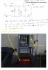
Voltage IN -------- Limiter ????? ------------ Voltage out
to 3.3VDC
keep it unchanged
if Vin < 3.3VDC

Thank you
 
Use a series resistor to limit current and a 3.3V zener from the output to ground. If high frequency noise is still a problem then connect a capacitor across the zener.

Mike.
 
If i have interpreted the OP question correct a Zener and resistor / capacitor will solve all his problems but it will not output 3.3V if the input falls below 3.3V which is what i think he was asking for?

Andy
 
If i have interpreted the OP question correct a Zener and resistor / capacitor will solve all his problems but it will not output 3.3V if the input falls below 3.3V which is what i think he was asking for?

Andy

The title of this thread contains the words, "unchanged if lower".

Mike.
 
Correct. The output should not be changed if value is lower than 3.3VDC.

Nevertheless this did not worked for me. After the output of the machine was stable, I really add close to 3.3VDC and I have tested the circuit with several DC voltages before connected it to the machine.
Connected to the machine, I had outputs quite large, and tryed several capacitors, but without any luck so I quited. Maybe will try later.

The machine is a plasma cutter, that have an initial high frequency arc. This is probably the problem.
 
For very severe electromagnetic interference, like the one you are experiencing, additional fixes may be required.

-The first is that the sensing wires must be shielded or at least twisted. You don't want your wires becoming an antenna.
-The second is that the common (return) wire for the sensing circuits must be grounded at a single point.
-The third is to add a common mode choke filter.
-The fourth is the types of capacitors...usually a 1uf tantalum in parallel with a 0.1uf ceramic will cover a wider spectrum range. Sometimes a third capacitor 0.001uf ceramic may be required. Keep leads short!
-The fifth: pray.
 
Last edited:
I will explain better my aproatch to the issue. The plasma machine is a metal cutting unit, that makes an high frequency arc (starting arc) until the cutting arc is estabilish. This final arc (cutting) can be up to 350VDC. During normal operation of the machine (during cutting) the circuit explained below is working fine, during the initial arc no.

For this reason I have made a simply voltage divider to target the range of my measure equipment, I have made more or less 100:1 voltage divider using 150K and 1.5K with a ceramic 10uF capacitor; more or less was this.

The amazing thing, was that during the initial arc, the output voltage (after the voltage divider) could be up to 200VDC (my inexpensive multimeter registed it), and this could be 3 things:

1) multimeter damaged - unlikelly;
2) That the input voltage was 100 times greather; so about 200*100 ?! unlikelly
3) Noise - probably

And probally noise is/was the reason. I made the voltage divider inside the machine, and maybe the wires after the voltage divider were piking up the frequency noise of the plasma unit. Maybe the voltage divider should be far away from the machine.

I have damaged one expensive piece and I did not tryed again, but I want to.
Any opinions are apreciated, before I make anything.

Thanks
 
If you can draw a rough diagram of the parts relative location and the connections between them, it would help greatly in making recommendations.
 
I have upload a diagram and a picture of the plasma unit with explanations about the location of voltage divider.
Up to 10VDC the measure equipment is not damaged, but my objective is to have it controlled up to 3.3VDC if the input voltage is up to 350VDC.

Thank you all for the help.
 

Attachments

  • voltage_divider.jpeg
    voltage_divider.jpeg
    328.1 KB · Views: 150
Status
Not open for further replies.

Latest threads

New Articles From Microcontroller Tips

Back
Top