Continue to Site

Welcome to our site!

Electro Tech is an online community (with over 170,000 members) who enjoy talking about and building electronic circuits, projects and gadgets. To participate you need to register. Registration is free. Click here to register now.

  • Welcome to our site! Electro Tech is an online community (with over 170,000 members) who enjoy talking about and building electronic circuits, projects and gadgets. To participate you need to register. Registration is free. Click here to register now.

lights help

Status
Not open for further replies.
go with LED's instead
LEDs will certainly stand up better to vibration, they light faster [which could shave off ~1/10 sec. from the response time of people in back of you who have to stop] and in some cases their service lifetime is ~100K hours.
 
Last edited:
This circuit will limit the current in the brakes lights to 30mA and the tail lights to 10mA.
 

Attachments

  • tail and brakes light.PNG
    tail and brakes light.PNG
    8.3 KB · Views: 137
This circuit will limit the current in the brakes lights to 30mA and the tail lights to 10mA.

I would make R3 210 ohms. This is based on 20mA draw (10mA/branch). If your 10mA is right (for It), then each branch will only draw 5mA. I think it needs to be brighter.
 
I added the currents wrong. Each LED in my tail light has only 5mA.
Your vision's sensitivity to brightness is logarithmic So the brake lights will look bright and the tail lights will look a liittle dimmed.

210 ohms is not a standard resistor value.
 
So do I still go with what the diagram says or do I need to change the resistors? also what is the R3 bit??? only see R1 and R2 on the diagram???? lol
 
I'd assume the LEDs put out ~5x the light for the same power as incandescents, which means equal brightness for 5x less power than incandescents.
 
Last edited:
So do I still go with what the diagram says or do I need to change the resistors? also what is the R3 bit??? only see R1 and R2 on the diagram???? lol

Sorry, I am referring to AudioGurus schematic. I made one up similar but decided not to post because AG beat me to it. He actually has R1 labeled twice on the schematic. These are the two referred to as R1/R2 in the branches. The series dropping resistor I referred to as R3 is R2 on AGs schematic. Change the 390ohm to 220ohm. Leave R1 and R2 at 220ohms.
 
oh I see what you mean now. Thanks for that.

I posted up on another forum the same time as I did here and one of the guys there said this

--------------------------------------------------------------------------------

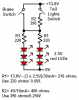
Here's a drawing of what you want to do, though you may use a different number of LEDs. If the resistors are the same value then the current will be approximately double when you hit the brakes. Assume you want 30 mA when you hit the brakes and 15 mA normally. The LED datasheet (N46AT) shows that typical forward voltage = 1.8 V when current = 15 mA (see the I-V graph on the last page). If your LEDs are typical, then 6 in series would make 10.8 V at 15 mA. Not sure what type of battery you're using but assume it's a lead acid, so about 12.6 V when full. That gives 1.8 V left over to drop across the resistor. You must choose the resistor that will give 15 mA with 1.8 V across it. 1.8 / .015 = 120 ohms. If the other resistor is also 120 ohms, you'll have 60 ohms equivalent (two 120's in parallel) when you activate the contact switch. 1.8 / 60 = 30 mA.

Now if you hook up your battery right after charging, the voltage will be higher and you'll get higher currents. So do the above calculation using the highest voltage you'll connect to the circuit. You want to be sure the LEDs don't see more than 30 mA with a full battery. As the battery drains of course the current will decrease and your lights will dim.

If your LEDs don't follow the typical characteristics you'll have to play around with the resistor value. Start high so you don't end up burning up the LEDs. Good luck

The drawing he gave me was this **broken link removed** which looks a bit more simple (to me anyway lol).

But after looking at it for a while I thought about the brake light needing to bypass the on/off switch (for daylight usage) and had a another thought about using 2 lights, one as a rear/brake light and the other as JUST a rear light.

I changed up his diagram a bit here **broken link removed** and wondered if it would work or not?

What do you think???
 
Yes, in practice it will work. But I wouldn't put all six in series. If you loose one, you loose all. I would stay with the original schematic AG drew up since all the values have been figured. If you feel it's too complex, you could try Willbe's suggestion below. This would be the simplest by far and give you the low/high light your looking for. The downside is it will use a lot more power. It will draw .57A for tail and 1.8A for brake if I remember correcly. You can refer to the data sheet to be sure. The brake current is a bit higher than the original bulb you have so your battery won't last as long. You can take a look and might consider getting a bigger battery. It's up to you, but if you feel up to the challenge of an LED light, that's the route I would take.

The 1034 and 1157 lamps have a high wattage filament (brake) and a low wattage filament that both get the 14.4 V from a running engine.
 
You received two different schematics because you posted two different stories:
1) Here you said you have a big LED that has six 2.5V LEDs inside.
2) On another website you didn't say the voltage of the LEDs so the other reply is just guessing.

Six 2.5V LEDs in series need 15V plus more for the current-limiting resistor. You don't have a voltage so high so you can't use six LEDs in series. I showed three in series plus another three in series which will work perfectly.

I showed the brake light always functional even in daylight like cars.
 
Six 2.5V LEDs in series need 15V plus more for the current-limiting resistor. You don't have a voltage so high so you can't use six LEDs in series.

I agree.

LEDs like constant current, so the bigger the dropping resistor is, the more nearly they are being fed constant current.

I doubt that the manufacturers control the Vdrop of LEDs; some might spec the range, though. They control LED current vs. brightness and live with what falls out on the other parameters.

The flashlights with no dropping resistors are probably severely stressing their LEDs, trading brightness [and sales appeal] for service lifetime.
 
You received two different schematics because you posted two different stories:
1) Here you said you have a big LED that has six 2.5V LEDs inside.
2) On another website you didn't say the voltage of the LEDs so the other reply is just guessing.

Six 2.5V LEDs in series need 15V plus more for the current-limiting resistor. You don't have a voltage so high so you can't use six LEDs in series. I showed three in series plus another three in series which will work perfectly.

I showed the brake light always functional even in daylight like cars.

That's a good point. I didn't notice, or rather care to notice, the Vdrop/Vsupply of the other schematic since I had predetermined that yours was the better design base on the information given. But one thing I should have mentioned, the author of the schematic from the other site should have speced it using super-bright LEDs.
 
Last edited:
You received two different schematics because you posted two different stories:
1) Here you said you have a big LED that has six 2.5V LEDs inside.
2) On another website you didn't say the voltage of the LEDs so the other reply is just guessing.

Six 2.5V LEDs in series need 15V plus more for the current-limiting resistor. You don't have a voltage so high so you can't use six LEDs in series. I showed three in series plus another three in series which will work perfectly.

I showed the brake light always functional even in daylight like cars.

I did say that I was going to use individual leds AND that I already had the large LEDs and asked if it made a difference but didnt get an answer to that question. I assumed you were basing it all on the individual LED's. Also I thought I posted a link to both the individual LEDs and the big 6in1 LEDs?! Which I also did on the other site.
Sorry if I didnt, thought I had.

Anyway, I will try out both lights and see which works better.
I'll post back the results as soon as thery're done. will be in a few days time cos have lots going on the next few days.
 
Last edited:
Status
Not open for further replies.

Latest threads

New Articles From Microcontroller Tips

Back
Top