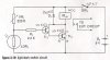
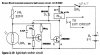
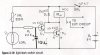
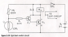
Ok, I added 2 more resistors and 1 small cap.
The relay transistor is the detector, the other transistor is inverse operation and provides hysteresis via the 1meg resistor.
To reduce the hysteresis use a higher value than 1meg, but I think the 1meg will work ok. It's been a few years since i built a light operated switch like this but those parts values look ok. It should switch clean and fast.
The value of the small cap can be anything, probably 0.1uF or less should be ok.
Note too if you are using a 9v battery and 6v relay you might want to put a resistor (R ?) in series with the relay to keep it's operating voltage at about 6v on the relay coil, this will use less battery power.

 Perhaps you can tell us what part you do not understand.
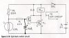
")