Continue to Site

Welcome to our site!

Electro Tech is an online community (with over 170,000 members) who enjoy talking about and building electronic circuits, projects and gadgets. To participate you need to register. Registration is free. Click here to register now.

  • Welcome to our site! Electro Tech is an online community (with over 170,000 members) who enjoy talking about and building electronic circuits, projects and gadgets. To participate you need to register. Registration is free. Click here to register now.

Light/ Darck, sound sensor problems

Status
Not open for further replies.

gvi70000

Member
Hello,
I need some help to create two sensors using LMV 721/722 OpAmp
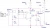
One will be a light/dark activated switch for one led and the other a sound activated switch. Both must have sensitivity adjustment.
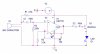
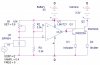
The light circuit I've manage to get it work only for the switch part (switching the In+ and In- of the op amp), the sensitivity one..no luck:(, as for the sound sensor nothing till now (the microphone is a capacitor one).
The supply will be a 3V Li battery.

Can any one please help me to solve these circuits?

Thank you.
 

Attachments

  • Light_Dark_LMV721.JPG
    Light_Dark_LMV721.JPG
    53.3 KB · Views: 831
  • Sound_LMV721.JPG
    Sound_LMV721.JPG
    47 KB · Views: 880
What LED will you get which you can light with emitter follower from 3V?

BPW34 generates what is better considered a current. The divider R1/R2/R3 makes no sense.

C2 blocks the return of base current on Q1.

Gain of 3 is not enough.
 
Hi,
thank you for the reply.
The led is a 3mm
I increase the value of R4 to get more gain and remove C2...no success
"The divider R1/R2/R3 makes no sense" i don't know what do you mean by that...sorry, i don't want to be rude, but i am a new in electronics.
with this circuit I'm trying a camera remote shutter release and the case is small, but i think it will accommodate 2 3v Li batteries.
Any help or guidance will be appreciated
Thanks
 
Last edited:
"The divider R1/R2/R3 makes no sense" because there would normally be a voltage source at the top of R2. If the top of R1 is also connected to a voltage source, then it would seem to me that the diode U1 is backwards. (Incidentally, BPW34 has only two terminals, not three, in the data sheet that I find).
 
What do you thing about this one?
in order to simulate the circuit, the third pin of the photodiode represent the excitation source

PS How can i attach more pictures to this post?

the pictures are here
**broken link removed**


I want to build a camera shutter trigger with a light and sound sensor.

When the microphone detects a sound the shutter is on. I need to adjust the sensitivity to not have false triggers. To see the threshold that triggers my camera i need the led (actually there will be one more transistor -same base as first one - that closes the camera trigger circuit)

For the light sensor i need two modes:
1. Trigger at lighting or other flashes (sudden light increase)
2. To trigger when a beam of light that falls on the photo diode is interrupted (to get nice pictures of water drops).

This is what i want to achieve.

Instead of photo diode i an use a photo transistor, but it has slower response and I've read that for this type of application BPW will do a better job.
 
Last edited by a moderator:
Hello,
I think I've made some progress here and i need your opinion
What I'm not able to do is to change the circuits sensitivity so i need some advices.
One more thing, do you think it is possible to increase the time of led (D1,D2) being lit without using a 555? If yes, how can i do it?

Thank you
 

Attachments

  • Light.JPG
    Light.JPG
    56.1 KB · Views: 302
  • Mic.JPG
    Mic.JPG
    58.9 KB · Views: 287
I think i get the sensitivity part working (not sure at all) on the light sensor but for the sound I've got nothing.

Please, it must be somebody out there who is willing to help me solve these problems

PS: I found somthing similar but it uses a micro-controller, maybe it will give you an idea https://www.doc-diy.net/photo/smatrig/
 

Attachments

  • Light.JPG
    Light.JPG
    63.2 KB · Views: 233
Last edited:
Status
Not open for further replies.

New Articles From Microcontroller Tips

Back
Top