Continue to Site

Welcome to our site!

Electro Tech is an online community (with over 170,000 members) who enjoy talking about and building electronic circuits, projects and gadgets. To participate you need to register. Registration is free. Click here to register now.

  • Welcome to our site! Electro Tech is an online community (with over 170,000 members) who enjoy talking about and building electronic circuits, projects and gadgets. To participate you need to register. Registration is free. Click here to register now.

Light Control with PWM (MOC3021)

Status
Not open for further replies.

macmmt

New Member
Hello,

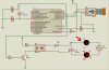
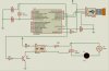
I'm trying to control the light of a bulb with PWM. I'm using a PIC 18f2550 since i have to send information to the computer through USB and receive the set point from it.
As optocoupler, I have a MOC3021 that is coneccting the control circuit with the power circuit. In the power circuit I use a Triac BT136.

As I change the duty cycle of the PWM, It is supposed to change the intensity of the light, but it doesn't work. The PWM is working alright. I guess the problem is something with the power circuit or with the optocoupler.

I would like you help me to determine where the problem is.

Thanks for your help.
 

Attachments

  • usb..jpg
    usb..jpg
    70.2 KB · Views: 24,528
Last edited:
You are sure you don't have the MT1 & MT2 terminals reversed?

Ron
 
I am really very bad at this kind of circuit, but I can see that firing the triac depends on having the "on" signal from the PIC synchronous with the sine generator and have variable time lag compared to the zero crossing point. How does the PIC know the phase of the sine generator? Without that information, the MOC firing signal from the PIC will have random phase information.
 
No. You're ahead of me now. I don't even know how a zero crossing detector would tell the PIC what to do.
I know I've seen a zero crossing detector chip because I remember looking at the drawing of its internals and understanding how it worked. I'd bet you can buy that chip, but I don't remember its number and I don't know how to use it in this circuit.

Next helper, please step up.
 
Ron was right. The light buld goes on the other side of the triac, sharing a connection with R5. Also, what is your PWM frequency ?
 

Attachments

  • Triac..jpg
    Triac..jpg
    115.4 KB · Views: 7,043
True, the light bulb was on the wrong side of the triac. I'd still like to know how the PIC finds the phase information.
 
No, you don't want PWM, you want phase control .

I think you're confusing the two.

PWM with mains is normally done at a lower frequency than the mains frequency and is suited to heaters but not lamps which will flash because the frequency is so low.

The algorithm for phase control goes like this:

Wait until the mains voltage is near zero (typically below 15V or so), start a timer.
When the timer finishes, fire the TRIAC.
Go back to the start.

The duration of the timer controls the brightness. The maximum duration is half the period of the mains frequency, in other words, t = 1/(2f). The longer the duration of the delay,, the later the firing, the dimmer the bulb will be, the shorter the brighter the bulb will be, if there is no delay and the TRAIC is fired immediately, you get full power.

A comparator is normally used for zero crossing, the AC voltage from a transformer (which is also normally used to power the rest of the circuit) is compared to the 0V rail, when the comparator is high or low (depending on which way round the inputs are connected) AC signal is 0V.

You need a small mains transformer so you can monitor the mains voltage. An opto-coupler also might work, connect the LED to the mains, with a reverse voltage protection diode in parallel, via a suitable series resistor and connect the photo transistor to an MCU input using a suitable pull-down/up resistor. The LED will only be activated when the AC voltage is above about +1.5V, this will turn the photo transistor on, letting the MCU know that the AC voltage has just passed through 0V, when the voltage drops below about 1.5V, the LED and photo transistor will turn off, letting the MCU know again that the AC voltage is near 0V. You can use either the on, off signals, or both, to start your timing delay, you only need to use one because you know that the mains will be near 0V again after 1/(2f).

There's lots of more information on Google.
 
Last edited:
hi,
Look at this pdf, in built ZCD.

Eric, he wants to dim the light so an opto-coupler with built-in zero crossing is not suitable.
 
Eric, he wants to dim the light so an opto-coupler with built-in zero crossing is not suitable.

hero,
The OP wants to use PWM, so a zero cross detector is required.

Please read posts before replying, you are just causing confusion.!
 
You've not read the whole post.

He wants to control the intensity of a lamp, which can't be done with PWM, using a zero crossing opto-TRIAC or any kind of TRIAC for that matter.

To control the intensity of a lamp he needs phase control, not PWM.

Please read the whole post before replying.
 
He wants to control the intensity of a lamp, which can't be done with PWM, using a zero crossing opto-TRIAC or any kind of TRIAC for that matter.

To control the intensity of a lamp he needs phase control, not PWM.

Please read the whole post before replying.

It can be done with PWM if the PWM is synchronised to the zero crossing point and is often done that way.

Dont say something cannot be done just because you dont know to do it.!

BTW: I do my best to give a reply thats in line with what the OP is asking rather what I think he should be doing.
 
Last edited:
That's no different to phase control because you're delaying the firing of the TRIAC.

You still can't use a zero crossing opto-isolator such as the MOC3081, as suggested by you, because it will only fire when the cycle is near 0V.
 
That's no different to phase control because you're delaying the firing of the TRIAC.

You still can't use a zero crossing opto-isolator such as the MOC3081, as suggested by you, because it will only fire when the cycle is near 0V.

Your missing the point of the MOC3081, its not to control the lamp but be used to give zero cross sync to the PIC.

Again you are using the word 'cant' when you mean, you dont know how.

Phase control is varying of the firing angle over the mains cycle in order to change the light intensity.
Are you getting confused with proportional control of the intensity, which would result in a flickering light.?
 
You should've made that clear, if the original poster substituted the MOC3021 with the MOC3081 in his existing diagram, it would not work.

What you mean by proportional control? Is that burst control which is PWM and is used for heaters which would make the lamp flash so totally unsuitable for an incandescent lamp control?

Please post a schematic, I can't guess at what you mean.

This is what the OP asked for and this what I told him.
Quote Originally Posted by macmmt View Post
Could you tell me a Zero crossing Detector Circuit?
hi,
Look at this pdf, in built ZCD.

Proportional control is commonly called burst control, NOT PWM

This is what I said in my last post, why did you think it was necessary to repeat it.??

Are you getting confused with proportional control of the intensity, which would result in a flickering light.?

I can see that you are either not reading whats been posted or you dont understand it.

I would suggest we stop hi-jacking this thread.
 
I can see that you are either not reading whats been posted or you dont understand it.
Speak for yourself.

The chances are this is a misunderstanding as in the other thread where you misinterpreted what I said but this time I'm not going to bother arguing with you, until you see what I mean.

Either way the following things are true:

Burst control is not suitable for dimming incandescent lamps, it will cause them to flicker.

You need to use phase control to control the brightness of an incandescent lamp withou it flickering.
 
hab u completed this projects?
simulation of moc3021 worked in proteus??
m very confused about the operation of moc3021. Does the output remains on even if we turn off the VCC supply..
how to switch the output off................
 
Status
Not open for further replies.

Latest threads

New Articles From Microcontroller Tips

Back
Top