Electro Tech is an online community (with over 170,000 members) who enjoy talking about and building electronic circuits, projects and gadgets. To participate you need to register. Registration is free. Click here to register now.
Welcome to our site! Electro Tech is an online community (with over 170,000 members) who enjoy talking about and building electronic circuits, projects and gadgets. To participate you need to register. Registration is free. Click here to register now.
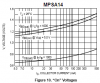
The MPSA14 is a darlington with a typical current gain of 60,000.
Motorola invented it and their datasheet shows a saturation voltage chart with Ic/Ib= 1000.
i just DL'ed and installed cadlite 3.5.9 so i have a schematic drawer now i'll have to mess with it a little i'm gonna have to find a friend with an inkjet printer though
cool. i'll do a couple more today a couple more npn's then for the pnp's till i get comfortable. for the next couple days or until i have the datasheets for all the transistors i have =)
i found a little compartmentalized box to put all my resistors and stuff in. the kitchen table loks nicer now haha!!
okay i've looked at the fair child and now at the motorola sheet for the 2n5551 fairchild said somewhere between 10 and 12. motorola says the same but in figure1 at 25d C and 20mA it says between 60@1vdc and 150@5vdc then in figure 4 it shows ic/ib=10 so which should i go with? everything points to 10 but i just want to make sure.
They show a base current that is 1/10th of the collector current when it is used as a saturated switch. Then all of them will work, even the weak ones that still pass the spec's.
okay from now on i will go with the higher HFE i find as they all 3 HFE's as audio said work and get the same results(brightness of the LED)
okay i got the switch for all my npn's working and proper i'm gonna do this same thing for my TIP42 and see if i can get it. then i don't know if'n i should go on to learning about bias and the amplification stuffs or if i should mess around with other types of transistors. like FET's and things like that! what do you guys think would be best?
This circuit uses the transistor as an emitter-follower. The pot adjusts the voltage to the base of the transistor and the voltage of the emitter follows it with a higher current. The pot adjusts the brightness of the LED.
awesome it works. i ad to use different resistors or a couple in parallel to get the proper resistance but it works. awesome. i'm gonna do some probing now to see just how it works.
one note on top-ramen noodles that stuff stay good for a while. but watch out for the bugs that might grow from it. i just learned my lesson on that and thought i'd share!!
okay i was reading about follower circuits. and from what i read HFE comes into play again and so does voltage saturation(sort of) for an HFE of 100 for every amp that does to the base the trans lets 100 amp go through the collector and the emitter. at a smaller voltage that concurs with the voltage saturation ratio/curve of the transistor. is this true?
A follower has a small base current from the pot and its hFE makes a higher current at the emitter.
The pot makes an adjustable voltage and the emitter follows it (but it is 0.7V less than the base). Then use Ohm's Law to calculate the current in the LED and in its current-limiting resistor. High current makes high brightness, low current makes low brightness.
okay i was reading about follower circuits. and from what i read HFE comes into play again and so does voltage saturation(sort of) for an HFE of 100 for every amp that does to the base the trans lets 100 amp go through the collector and the emitter. at a smaller voltage that concurs with the voltage saturation ratio/curve of the transistor. is this true?
This site uses cookies to help personalise content, tailor your experience and to keep you logged in if you register.
By continuing to use this site, you are consenting to our use of cookies.