Integraoligist
New Member
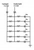
I'm creating my own tail lights for my car using these LEDs:
10mm Red
40,000 mcd
12 degree
(typical V and A i do not have yet, i will post as soon as i get them)
Side notes to this schem. During the day, the "Tail light" is not ON, so it reads 0V however when the brake is applied the "Brake light" will read 12V.
Night time, "Tail light" will be ON reading 12V and when the 12V "Brake light" is applied, both the Tail and Brake lights will be outputing 12V.
Does this schem. look correct? I did not add Voltage regulators because the resistors will be large enough to handle any Voltage "Spikes"
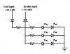