Continue to Site

Welcome to our site!

Electro Tech is an online community (with over 170,000 members) who enjoy talking about and building electronic circuits, projects and gadgets. To participate you need to register. Registration is free. Click here to register now.

  • Welcome to our site! Electro Tech is an online community (with over 170,000 members) who enjoy talking about and building electronic circuits, projects and gadgets. To participate you need to register. Registration is free. Click here to register now.

LED Switching Regulator

Status
Not open for further replies.

Hero999

Banned
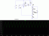
I was bored at work and had an idea so I started playing around in LTSpice and came up with this circuit to power a couple of LEDs from a 12V battery.

I can't believe how simple it is. This is an example of a Schmitt trigger LR oscillator, the only difference is, the current in the inductor is also being used to power some LEDs. It uses a comparator with hysteresis to turn on Q1, causing the current in the inductor to increase, until the voltage across R1 is enough to turn it off, causing the current in the inductor to flow through D3 and the LEDs, until it drops enough to turn the comparator back on again. I'm sure this has been thought of before but I've only seen this type of design in voltage regulators, not current regulators.

You can use any comparator you want, the LM311 will probably do but if you want to drive a MOSFET, you'll want to use a comparator with a push-pull output and a N-channel MOSFET.

This circuit uses a switching frequency of about 160kHz and a huge ripple of 160mA (this is no problem for an LED) and an average current through the LED of 280mA.

This circuit is a simple, cheap and relaiable alternative to using a special LED drive SMPs IC. I haven't built it yet, hence this is why it's in the theory section but it should work very well.
 

Attachments

  • LED SMPs.GIF
    LED SMPs.GIF
    21.4 KB · Views: 2,607
Last edited:
That is close to what most of them do anyhow.

The piece of crap from Maxim uses a high side current sense and low side NFET to do hysteretic.

The HV9910 uses an NFET and low side drive to implement either constant frequency or constant off time peak current control.

Dan
 
Then why bother with a specialised IC when a cheap comparator and transistor will do most of the time?
 
Well that depends on what you are trying to do. The HV9910 actually has a lot going for it: it is under $1.25 in single piece qty and has a 450V LDO on chip, linear and PWM dimming inputs, and a multifunction oscillator block.

Now why anyone in their right mind would use a MAX18620 that costs $0.90 in 2500pc reels and are not available any other way.

Dan
 
Then why bother with a specialised IC when a cheap comparator and transistor will do most of the time?

As ubergeek said, depends on what you want to do, what efficiency you need, and what your power supply range is. Of course you did say 'most of the time', which I can agree with.

I'll also agree that SMPS circuits can be very simple..and even simpler if you need to light a couple of white LED's from 1.5v using a switched capacitor circuit...two transistors and a few passives... but efficiency suffers.

Many contain the built in switch with a very low RDS on, improving efficiency, and reducing package size...as well as running at high frequencies, reducing the size of the inductor and therefore reducing the footprint.

A nice 'in between' solution from your simple, but effective switcher, and a specialised chip, is a 8-pin micro, like a PIC. More than enough resources for making a very versatile buck/boost PSU, with goodies like UART/SPI/I2C interface.

Nice circuit though!

Blueteeth
 
I forgot one critical detail about the piece of crap from Maxim: The chip blows out if you accidentally short the current sense input to ground!
 
As far as efficiency is concerned, if you use a transistor with a high beta, low saturation voltage, a Schottky diode, a low ESR inductor and a low value sense resistor, it shouln't be too hard to get >90% with this simple circuit. I've done a few quick calulations based on the losses in the resistor, transistor and diode and come to a figure of about 94% but it'll probably be slightly worse than this.
 
you might actually find it hard to come close to 90%. A common mistake is to assume the diode drop of a schottky is 0.3V, which is already close to 10% of a single white LED drop.

Most schottkys are actually close to 0.5V or more at their rated current. If you are running from a high voltage your duty cycle will be low and the schottky losses will dominate.

If, for instance, you are running a single white from 36V at the rating of the schottky you will have around 0.5V loss 90% of the time, or about a 10% loss due to the diode alone. In this case a synchronous converter can not be beat.

Dan
 
Actually, I have considered that. I always try to grossly over rate Schottkys so the voltage loss is really low. My estimate was based on SPICE simulations and was just a rough guess, I didn't do an exact calculations. I jusr looked at the figures spat out by it.

The Schottky I've used in the simulation is rated for 3A and it only passes a maximum of 369mA which is 13.2% of the rated current.

The loss is only 288mV at the peak current draw and 261mV just before the transistor turns on which gives an average of only 275mV; this is <10% of one LED drop and <5% of the total LED drop in this circuit.

The transistor saturation loss is between 83.1mV and 103.2mV giveing an aveage of only 93.15mV.

The duty cycle is 63.5%.

The rise time is 6.7ns.

The fall time is 28.8ns.

The over all period is 6.309µs.

The inductor ESR was just set to 1mΩ which I know is far too low and needs increasing but my guess took account for this. I could do some more accurate calculations but there's no point with SPICE, it's much better to build the circuit.
 
Last edited:
Here's a version made with discrete components, it' isn't as efficient but it's cheaper.
 

Attachments

  • LED Switched Mode Power Supply.pdf
    27.6 KB · Views: 1,548
Powering other things than LED

Here's a version made with discrete components, it' isn't as efficient but it's cheaper.

Hero999, I'm going to try and build something that will collapse a coil I need in an experiment.

Just Off and On at a frequency does not have to be exact. I just need the coil to give a magnetic field.

Is it possible to use some op isolators with a Triac or something. Using this circuit.

Thanks in Advance. kv
 
I don't understand the question or how it relates to this circuit.

What do you mean collapse a coil? A sledgehammer will easily do that.:D
 
I don't understand the question or how it relates to this circuit.

What do you mean collapse a coil? A sledgehammer will easily do that.:D

Sledgehammers got one it will do I guess.

Thanks. kv

I Like the circuit good job.
 
Last edited:
Hi,

I just googled and came to know that switched mode power supply for LEDs is much efficient than directly hooking them up with powr source and LEDs are much brigher as well. I was looking for switched mode LED driver circuit and saw this thread


I have an LED pannel in an emergency light in which 60 LEDs are connected in parellel, they are driven through a 6 volt 4.5AH battery with one 2ohm 5watt resistor in series. They best operate when 1A current is flowing.

LEDs have forward voltage of 3.4V and current 16ma

If you know any cuircit that could support that number of LEDs and current please tell me, it will be great.


I'm a rookie as far as electronics is concerned, you help will be really appreciated.

Thanks,
Rizwan
 
It's possible if you make a couple of modifications, you can either lower the reference voltage or reduce R1. R2 needs reducing to allow enough current to saturate Q1.

Your best option is to use a comparator with a push-pull output and a MOSFET.

If you must go for a BJT then use a good quality one like the ZTX753 or the 2SA1943. It needs to have a low saturation voltage, high beta at 1A and fairly fast Ft >20MHz.


If you coult give a schematic and little description with it then that will be great :D
 
The schematic is on the first post in this thread.
 
All you need to do is change some of the component values. The post I made at the bottom of page 1 of this thread should give you a few clues as to what you should change.

I also forgot to say that you need replace the two series LEDs with your 60 LEDs in parallel but include a low value current ballancing resistor in series with each LED.

A lot of it depends on what components you have available. Try simulating it on LTSpice and playing around with it a bit.

Do you understand how it works? I tried to explain it in my first post but don't hesitate to ask if there's anything you don't get.
 
Hi,

I just googled and came to know that switched mode power supply for LEDs is much efficient than directly hooking them up with powr source and LEDs are much brigher as well. I was looking for switched mode LED driver circuit and saw this thread


I have an LED pannel in an emergency light in which 60 LEDs are connected in parellel, they are driven through a 6 volt 4.5AH battery with one 2ohm 5watt resistor in series. They best operate when 1A current is flowing.

If they don't have series resistors for EACH string or device in parallel, the device will fail. Not one big resistor in series with the combination of parallel strings. The LEDs will not play nice and share current, the hottest one actually takes more current (negative temp coefficient of forward voltage), heats up more, takes even more current, blows out. Then the rest start going out.

HV9910 is an excellent switching reg. Don't give it an overly huge transistor with large capacitances. ZXLD1350/1360/1362 also great, and those have internal transistors.
 
Status
Not open for further replies.

Latest threads

New Articles From Microcontroller Tips

Back
Top