Continue to Site

Welcome to our site!

Electro Tech is an online community (with over 170,000 members) who enjoy talking about and building electronic circuits, projects and gadgets. To participate you need to register. Registration is free. Click here to register now.

  • Welcome to our site! Electro Tech is an online community (with over 170,000 members) who enjoy talking about and building electronic circuits, projects and gadgets. To participate you need to register. Registration is free. Click here to register now.

LED Strobe

Status
Not open for further replies.

JaXoN

New Member
Anyone can help me with this circuit? Making this circuit for RC.
I want a LED strobe that blinks twice or more at a time on each side. Means LL RR LL RR.. I want it to be support by a 9v battery.
Thanks u :oops:
 
I think the most simple way would be to use a multivibrator (i think thats what you call 'em). It can flash two LEDs. If you use blinking LEDs, you can wire it up so that the each LED stays on long enough for two flashes.
 
Just make a blink oscillator and a side-to-side oscillator. Gates controlled by the oscillators can drive the LEDs with transistors.

A counter output from a CD4060 can be the blink oscillator and another output from its counter can be the side-to-side rate.
A CD4011 can make a gate for one side and an inverter for the other side. :lol:
 
I think no one is understanding him. He wants the sequence as follows:

Left light blinks twice, right light blinks twice and he wants to use 2 LED's.

Your best bet is to use a decade counter. Connect Q0 and Q2 to one LED, and connect Q4 and Q7 to the other LED. The speed is determined by the external clock which the above posters commented on.

the other end of the LED's can be tied together, and connected to ground through a 300+ ohm resistor. The higher the resistance, the lower the brightness, but don't make the resistance too low or something will overheat.
 
mstecha, i thinking about some similar...
 

Attachments

  • blinker.gif
    blinker.gif
    4 KB · Views: 1,369
Hi Sebi,
Your blinker circuit is another way to do it but:
1) A Cmos gates oscillator has an output much closer to a 50-50 square-wave if only one of its inputs is used and the other input is disabled.
2) With a 9V battery, a Cmos gate has an output current into an LED of only about 8mA, so a current limiting resistor isn't needed and the LED won't be very bright without a driver transistor.
 

Attachments

  • blinker_changed.gif
    blinker_changed.gif
    4.5 KB · Views: 1,053
Thanks for your reply guys.
But still not so understand..
Can it be support more than 2 leds?
Example the 555 flasher circuit can support up to 18 leds with parallel connection. But it only can flash once at a time with alternate.

mstechca was right, left light blinks twice, right light blinks twice and i wants to use more than 2 LED's.
Something like this.. but not for cars, but for 1/10 scale radio control cars.
**broken link removed**

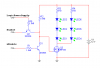
I found this. This circuit flashes Left,Right,Left,Right or Left,Left,Right,Right?
**broken link removed**
 
MStechca's idea has outputs of the counter shorted together so I don't think anything will blink except maybe the battery. :roll:
Sebi and I fixed it with diodes.

It is not recommended to connect LEDs directly in parallel. They all have a slightly different voltage so the one with the lowest voltage will hog all the current and burn out. The rest will also burn out in sequence. A current-limiting resistor should be used in series with each LED.

If the supply voltage is high enough and the LED driver saturates well, LEDs can be in series and use only one current-limiting resistor. A 9V battery's voltage drops to 6V over its life so you can use two 2V LEDs and a 200 ohm current-limiting resistor in series and have them driven by a transistor. They will be bright at 24mA with a new 9V battery, dimming to 10mA when the battery is finished. A little 2N3904 transistor can drive 8 of these strings of two LEDs and a 200 ohm resistor from a 9V battery but the battery won't last long. :lol:
 
hi to all..... i'm new, really NEW here.....

in case anyone's still interested, the circuit requested by JaXon which uses the CD4060 as adviced by audioguru can be found here.... http://www.cpemma.co.uk/blink.html

sorry to post the direct link but it works to the dot as requested by JaXon for an alternating 2-flash per LED. in order to get the 2 LEDs to alternate, just replace diode D1 with another LED in the polarity of D1.

moving R3 from pin 4 to pin 6 and retaining all other components and pin connections will get you the standard 4-flash per LED alternating between the 2 LEDs, hence you get an instant police flashing lights.......

in this respect i am trying to increase the output of pins 6 and 7 so that i can drive 10 or more Lumileds Superflux LEDs but i dont think any totem-pole drivers can have its output in a push-pull manner? or can it?

i would appreciate any advice on this. i can be contatced on my email at peterlm@streamyx.com or any replies made in this thread is most welcomed.

many thanks in advance.
 
Hooking up the LEDs between the outputs is a "free" way of implementing an "AND" and a "NOT" gate. To implement this discretely, you can use a diode and a pull-up resistor to as an "AND" gate, and a common-emitter NPN to make a "NOT" gate. The output of this discrete gate goes off to a bigger power transistor.

Last time I checked, superflux LEDs maxed out at ~70mA, driving these in series would be pretty easy with most NPN's, or just grab some off the shelf Mosfet if you want to crank out a 700mA pulse.
 
thanks for the reply there, hjames! yes, the Lumileds Superlux are great little LEDs and i have tonnes of them yellow green, turquoise green, blue and red ones from a scrap dealer! i also have tonnes of red and amber Lumileds I emitters which i have made for off-road 4x4 camp lighting..... i dont know what to do with the other bunch of SnapLEDs though, maybe brake lights? they're called scrap but they work just as well and at a fraction of the cost of new ones! hehe......

being the half-cooked electronics hobbyist that i am, i must ashamedly ask if you might be able to help put this into perspective by letting me know how exactly to connect the diode, pull-up resistor and transistor? a rough schematic or maybe explanation by specifying the where the compnents goes into the pinouts.

thank you very much again for your contribution and help!
 
This should work - instead of using a diode, I just threw in another transistor hooked up as a level converter. The general idea is that the main switch mosfet (or you can make it a NPN transistor if you want) only turns on if both Q1 and Q2 are off. Now, Q1 is pretty obvious when it turns on, Q2 is a little bit less so, but you should be able to figure that out.

Resize R3/change the number of LEDs in each chain as needed.

discrete TTL logic is fun once in a while.
 

Attachments

  • discretelogic.png
    discretelogic.png
    5.2 KB · Views: 618
Use a uC. Buy a 16F628 or 16F877, build a programer and satrt learning about pics:D
If u realy want to let the circ there buy a cheap 12F683 or so. Google for LED blinkers with 12F683 and/or 12F675.
 
Last edited:
thanks for the time taken to dsesign the drive circuit, hjames! i'll give it a go to see if that will solve my headache.... hehehe

and also thanks to tarsil for the advice on using a PIC which is way more flexible. yes, i did browse the web and found many sites with source codes for many types of LED drivers and i am really tempted to get onto PIC but have no expeirnce working with them. in fact i bought a PICAXE 08M but have not tried it out yet!

cheers.
 
Police Strobe

Im new to Rc Electronics so i was wondering if someone can reply instructions on how to make a lightbar And all the other strobes and flashing lights on the car

The car im using is a Skyline TT01 190mm 1/10 scale the skyline i got is from Tamiya so it already has holes for LED in headlights Turn Signals And Tailights and Rear Turn Signal if you would like to reach me my email is (jmtrvenom19@aol.com) but without the ()
 
Last edited:
Status
Not open for further replies.

Latest threads

New Articles From Microcontroller Tips

Back
Top