Continue to Site

Welcome to our site!

Electro Tech is an online community (with over 170,000 members) who enjoy talking about and building electronic circuits, projects and gadgets. To participate you need to register. Registration is free. Click here to register now.

  • Welcome to our site! Electro Tech is an online community (with over 170,000 members) who enjoy talking about and building electronic circuits, projects and gadgets. To participate you need to register. Registration is free. Click here to register now.

Led segment values?

Status
Not open for further replies.

Doomguy42

Member
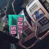
Hi, I had this old 1990ish display board on an old retro machine- where some of the segments were faulty. I checked all the wiring and drive components.
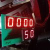
I couldn't find any datasheets for the original spec so I tried some from another display board from 1997... pinouts were the same. It works OK now, its brighter than the original x2 led left on there.

Will it be OK to continue using and is there anyway I can work out the value needed if it's incorrect? Not sure if there's any extra draw through my main board or anything like that.

Thanks
 

Attachments

  • received_3302917566597831.jpeg
    received_3302917566597831.jpeg
    356.2 KB · Views: 134
  • 20221213_205852463.jpg
    20221213_205852463.jpg
    1.3 MB · Views: 142
Simply too little info to answer your question. You could use a shunt in digit drive
line along with an oscilloscope to measure current if drive multiplexed, if not
multiplexed ordinary DVM would do the trick to see what current looks like.


Regards, Dana.
 
Perfectly fine, a later LED is probably more efficient.

We use a particular (and peculiar sized) LCD module in one of our products - and the other year they updated the modules. One change was to the backlight LED's, which are more efficient, so I changed the resistor feeding it so as to reduce battery consumption.
 
Simply too little info to answer your question. You could use a shunt in digit drive
line along with an oscilloscope to measure current if drive multiplexed, if not
multiplexed ordinary DVM would do the trick to see what current looks like.


Regards, Dana.

Your instincts to question your replacement also well founded, to make sure
your drive kevels not compromising other parts like a processor and its I/O
buss current limitations. If there is no safety aspects involved you can just throw
the dice and run with it.

But checking current to make sure there is no major deviation good design practice.


Regards, Dana.
 
I would test just one segment of the old display with a 5V supply, a resistor to limit current, and a multimeter. See what current it uses at your old "normal brightness". Then do the same with one of the new display segment. If the brightness is brighter but uses about the same current as the old module at that brightness, then you should be ok.
Nigel is probably correct in that the newer device is more efficient
 
The segments are red, so old and new displays will have approximately the same Vf. Either current is limited by series resistors or (less likely, considering the age) some kind of driver chip providing constant current. How could the current be significantly different?
 
Hi thanks for all the replies, the LED segments are multiplexed, one side is darlington transistors and the same drive as filament lamps-limited by a final resistor. The other side is driven by smaller transistors also then limited by resistors. So would that mean the total current is limited and not to worry?
I know modern LED indicators are super bright compared to older but just thought I'd better look into these being brighter.
I will use a phone charger and measure the current on one of each on my bench if that's acceptable?
Yes, as I said in the first place, it will be fine - danadak isn't interesting in helping people, just in showing off how clever he is.
 
Hi thanks for all the replies, the LED segments are multiplexed, one side is darlington transistors and the same drive as filament lamps-limited by a final resistor. The other side is driven by smaller transistors also then limited by resistors. So would that mean the total current is limited and not to worry?
I know modern LED indicators are super bright compared to older but just thought I'd better look into these being brighter.
I will use a phone charger and measure the current on one of each on my bench if that's acceptable?
Yes thats fine.

By the way, for future design work, this comes in quite handy if you are doing a lot of USB stuff :


Allows you to measure all power, V, I, on usb powered designs. Many standard usb connections.

Probably a simple hack to use non usb powered stuff with a USB breakout plugs.

2-3 apps to use with it over BLE. Pretty handy.


Regards, Dana.
 
Status
Not open for further replies.

Latest threads

New Articles From Microcontroller Tips

Back
Top