Continue to Site

Welcome to our site!

Electro Tech is an online community (with over 170,000 members) who enjoy talking about and building electronic circuits, projects and gadgets. To participate you need to register. Registration is free. Click here to register now.

  • Welcome to our site! Electro Tech is an online community (with over 170,000 members) who enjoy talking about and building electronic circuits, projects and gadgets. To participate you need to register. Registration is free. Click here to register now.

LED PCB Module

Status
Not open for further replies.

alok1982

Member
I am designing a PCB for LED module.

Where I am using three strings of LED. Each string have three LED's.

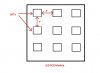
I just want to know that what distance I kept in between two LED's while placing in the board. i.e. distance "a" and "b".

Attached diagram will give you clear idea.
 

Attachments

  • LED PCB Module.jpg
    LED PCB Module.jpg
    31 KB · Views: 144
Hy alok,

Presumably, you are concerned about heat dissipation, but without knowing the type of LEDs you are planning on using, or the current level you will be driving them at, an answer to your question would be difficult, but as a rough stab I would think that a minimum spacing of the radius of the led would be adequate.

In general though, the important thing is to keep the LED junction temperature below the data sheet absolute maximum. To do this you need to lose heat from the LED by conduction and convection.

Conduction relies on contact with a heat sink which can comprise the traces on a PCB. It follows, therefore that the traces should be made as thick and wide as possible.
Convection relies on the free flow of air over a hot component, bearing in mind that convection currents flow upwards as hot air is lighter than cold air.

spec
 
OR

Maybe you are concerned about how the LEDs will be placed on the PCB.
Machines that place parts need some distance between parts.

Because I don't know what you are asking, I don't know how to answer.
 
I just want to know, for mounting LED on LED PCB how much distance I should keep in between two LED's.

Where LED PCB = the metal clad PCB where LED's is arranged in series or parallel configuration. And one terminal of this LED PCB is connected to LED driver for power up.
 
There is a picture from EAGLE CAD.
You can see a resistor, capacitor, resistor and 1/2 of an IC.
There is a red line around around each part. That is the "keep out area".
I have it set so there is 0.01 inch space around the parts. So the distance between parts is about 0.02 inches.
This is dependent on the machine that puts the parts on the board.
This is what I use.
upload_2016-4-19_17-49-39.png
 
Status
Not open for further replies.

New Articles From Microcontroller Tips

Back
Top