Continue to Site

Welcome to our site!

Electro Tech is an online community (with over 170,000 members) who enjoy talking about and building electronic circuits, projects and gadgets. To participate you need to register. Registration is free. Click here to register now.

  • Welcome to our site! Electro Tech is an online community (with over 170,000 members) who enjoy talking about and building electronic circuits, projects and gadgets. To participate you need to register. Registration is free. Click here to register now.

LED fading ambulance effect

Status
Not open for further replies.
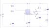
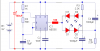
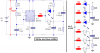
Hi guys, I am not an electircian or electronics engineer but I do know how to follow schematic diagrams... could anyone help me build a 4-LED ambulance effect??? it's like a strobe light, the difference is, it's a fading effect... 2 LED are lit together then fades while the other pair start to light... unlike the strobe light which flashes...
the LED to be used are either 4 pcs. 5mm or 3mm to be powered by at most a 9V battery...
NOTE: I do not have knowledge neither the resources how to program IC's or anything like that or even the microcontroller thing.

thanks in advance.
 
amb555-jpg.12432


Something might work, breadboard it and experiment.
 

Attachments

  • Amb555.jpg
    Amb555.jpg
    61.8 KB · Views: 691
Hi Harvey,
The 555 has an output current rating of 200mA but is capable of more until it is destroyed.
Your LEDs do not have anything to limit their current so they will probably blow up.
The capacitors have a very high ripple current so they are in a race with the LEDs and the 555 to see which will blow up first.
 
220 ohms in series with pin 3 of the 555 would help a lot. Certainly not for a production design, but it would probably outlast the novelty effect.
 
Ambulance lights.

Hi Grandmasteralok,

You might need to tweak the circuit a little more to get the precise
effect that you want. Especially both 4k7 and the 1k resistor, and
also the 330µF capacitor. I used only two red diffuse low current leds,
the other two should be connected in series with the ones that are
already in the circuit.
Note that I've never seen an ambulance like that. :confused:

on1aag.
 

Attachments

  • Ambulance.GIF
    Ambulance.GIF
    9.9 KB · Views: 241
I have seen ambulances in old movies with huge incandescent lights that try to flash but they take so long to heat and cool that they appear to fade.
 
mneary said:
220 ohms in series with pin 3 of the 555 would help a lot. Certainly not for a production design, but it would probably outlast the novelty effect.

do i still need to add the 220 ohms if i will add 2 more LED's (1 on each existing LED in Harvey's circuit)... is it resistor, capacitor, or what???

harvey, thanks for the schematic... it's pretty simple and i think is easy to build... but can you please provide the list of the materials??? i'm not familiar with the symbols... i only follow building the circuit by looking at labels and values... :D :D :D
 
I fixed Harvey's schematic, made it much smaller and made it a very clear PNG file type instead of a fuzzy JPG.:D

Use red LEDs because two white or blue ones won't light with only 9V for the supply.
 

Attachments

  • amb555.PNG
    amb555.PNG
    31.9 KB · Views: 387
I just threw together a quick astable, used the capacitor/resistor scheme elsewhere. Current limitting on the LEDs shouldn't be a huge concern, mostly they just drain the capacitors. Might cause a little strain when they first flash on, but it's quick and not continuous.

This was a 'just to get you started' circuit, the values shouldn't be too critical, and you need to make some adjustments to get the effect you want.
I'd go with Audioguru's work, he's good with details. Mine took maybe 5 minutes to enter and post, just stuff I had recent worked with thought it would be close.
 
Nah, I wouldn't worry about current limiting on the LEDs either, the internal resistance of the 555 should limit the current to a safe level, especially if it's CMOS and being run from a 9V battery.
 
A Cmos 555 has assymmetrical low output current. They don't have spec's with a 9V supply. The max source current is about 10mA and the max sink current is 50ma. Its typical current is less.

An ordinary 555 has symmetrical source and sink currents exceeding 200mA.
 
audioguru said:
I fixed Harvey's schematic, made it much smaller and made it a very clear PNG file type instead of a fuzzy JPG.:D

Use red LEDs because two white or blue ones won't light with only 9V for the supply.

wow this is great... thank you so much... too bad i am only limited to red lights??? how bout if i use 4 3mm LED (all white or 2 white and 2 blue)... can i then use 9v source??? i'll do this one first and try the 3mm LED once you've replied... thank you so much... :D :D :D
 
You can use white and blue LEDs with a 9V battery powering the circuit if the LEDs have their own separate current-limiting resistor. The 555 can drive many LEDs this way until either the 555 or the battery gets too hot.
If they get hot then they won't last long.
 

Attachments

  • white and blue LEDs.PNG
    white and blue LEDs.PNG
    54.6 KB · Views: 312
On second thoughts I didn't notive the size of those capacitors, with capacitors that large a current limiting resistor would be requited but if you replaced them with smaller values it wouldn't.
 
Big capacitors cause fading. Little capacitors cause blinking. We want fading.

My "flashlights" (Canadian torch) blink their ultra-bright LED 5 times for 20ms per flash, then have a 1/2 second pause. I cram 90mA into them and they are extremely bright. The 9V alkaline battery lasts a long time. White and blue LEDs have a forward voltage of about 4.5V at such high current and the 5V low-dropout regulator keeps them looking like new until the battery is nearly dead.

My 'mood-lights" fade 3 colours at slightly different speeds so there are all colours and all brightnesses shining on the ceiling changing slowly. The peak current is about 80mA per LED and the LEDs are rated for 30mA max continuous.
 
audioguru said:
You can use white and blue LEDs with a 9V battery powering the circuit if the LEDs have their own separate current-limiting resistor. The 555 can drive many LEDs this way until either the 555 or the battery gets too hot.
If they get hot then they won't last long.

this is great... can't wait to try this one out... thank you so much guys... hopefully, i would post a video of the finished circuit... (i just hope i would follow the diagram correctly... :D :D :eek: :eek: )
 
Should be easy to build. Just need to watch the polarity of the big capacitors and the LEDs. Those to things sometime cause problems for people with lots of experience. Just take your time, double check stuff. This circuit should be pretty forgiving, shouldn't be a lot of fire and smoke if you do make a mistake.
 
Status
Not open for further replies.

Latest threads

New Articles From Microcontroller Tips

Back
Top