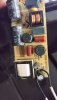
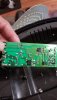
I think the board is a switch mode constant current power supply for the LEDs. I think the bridge rectifier is the square component with 4 pins on the etch side of the board. (About the bottom middle of the picture in post #6) I
Less when you say trace out the schematic of the board, what exactly do you mean? Thank you