Continue to Site

Welcome to our site!

Electro Tech is an online community (with over 170,000 members) who enjoy talking about and building electronic circuits, projects and gadgets. To participate you need to register. Registration is free. Click here to register now.

  • Welcome to our site! Electro Tech is an online community (with over 170,000 members) who enjoy talking about and building electronic circuits, projects and gadgets. To participate you need to register. Registration is free. Click here to register now.

led automotive interior light help

Status
Not open for further replies.

chris_19

New Member
i bought a led interior light for my car but keep getting a slight back-feed enough to power the led very dimly when its only on door mode i tried putting a diode on the wire for body module which is where door wire hooks up too it that never worked

inside the light there is (6) 200 ohm resistors per 18 smd led lights which total there is 36 led smd lights and 12 resistors which are all 200ohm

my understanding is there isn't enough resistance for the light when body module is active that it powers the light up through the body module dimly when i tested the wires 12v which is supply roughly 1v is the door when its active then it drops too about 0.4-0.5 volt and stays there and then ground which is grounded to the chassis

would i need to change the smd resistors on the board to higher resistance like 300-400 ohm for it too stop the dim issue or would installing a capacitor like 10v work?

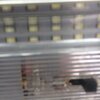
attachment picture is the issue im having when vehicle is in accessory's or run
 

Attachments

  • IMG_0327.JPG
    IMG_0327.JPG
    494.8 KB · Views: 165
Try connecting a resistor across the light (in parallel with it) so any slight leakage current does not create enough voltage to illuminate the LEDs.
I'd try a 1K resistor to start with, a 0.5W or 1W one.

Changing the built-in resistors would dim the light but probably have little effect on the unwanted illumination.
 
what u mean across the light been there is 3 wires 12v ( door mode) ground i did try n put a 1k resistor on the door mode side of the wire light wouldn't turn on with door mode i think the tolerance for the resistor was 5% not sure the (w) of it tho i tired different resistor could it possible be the resistors im using are very tiny ones i think there like 1/4w ones
 
I have no idea what your trying to say. let me explain what happened when I upgraded the interior and trunk lights from incadesent to LED. it might help you. The car is a Chevrolet with "retained power". e.g. When you turn the ignition off, the interior lights and radio continue to work until the door is opened. There is dimming when the car starts and the lights dim when they turn off.

The lamps were like 193 and the trunk was a 194, I think. The trunk was upgraded first and for quite some time. That worked.

When I added the interior lights. 2 plus two in the drivers mirror (map lights) which had independent switches.

When I had the door open and the trunk open, the lights would turn off after some specific time to save the battery/

When I closed the driver's door and opened it, the trunk came on at 1/2 brightness. I had to close all of the doors and trunk for the system to work properly.

What did I do to fix it?

You have to also remember that incadesent lamps have a resistance that could be 10x lower when they are off, then when they are on.

What did I do? I found the current requirements for the trunk bulb, the current for the LEDS and found a resistor to make up the difference. I paralleled a power resistor under the rear deck and all is well. i don't really have to worry about it working forever, so being sandwhiched between some insulation was no big deal.

LED's only pass current in one direction. I forget what value of resistor I used, but it was a chassis mount 3-5 Watt version.
 
Last edited:
They do not make cars since about 20 years ago; they make computers with wheels. And even interior lights are controlled by a 'body control unit' which does not recognize the tiny current load from a LED emitter instead of the expected incandescent bulb. Then the computer goes bananas.

Better desist of the upgraded light, or increase the load until the computer feels pleased again.
 
The interior light is controlled by a module that does not shut off completely, so when it is off, there is still some residual current flowing. If you have the original incandescent light fitted, the residual current will not be enough to get the filament hot enough to glow, so no light will be seen.

That same amount of residual current will make the LEDs glow. You need to bypass that current by putting a resistor in parallel with the lamp. Then the residual current flows through the resistor, and if the resistor is a small enough value, there will be too little voltage to make the LEDs illuminate.

The problem with LEDs glowing when they are supposed to be off is so common that many LED lamp assemblies contain the bypass resistors. They sometimes have the additional benefit of preventing false warnings for lamp failure. LED assemblies with bypass resistors are named "CANbus compatible" or similar.

(It's nothing to do with the CANbus or any other communications buses in the cars, but the bulb failure detection systems became common at much the same time, give or take a decade or so, as CANbus became common in cars, and the fault codes are often read on the CANbus, and a general lack of understanding of the systems meant that they got associated with each other)
 
according to factory bulb specs amps is 0.740 voltage is 13.5 watts is 10, so been that factory OEM bulb is 10w i would need a resistor that is 5w, since the total wattage of the led (smd) dome light is 5w and put that resistor parallel which would be the body module wire to the black wire which is ground or would i just have the resistor on the body module wire that runs to light and the wire that comes off the light and put resistor inline there?
 
Assuming your numbers are right. There are details that I'm not worrying about. e.g. Voltage should be 13.6V.

So, with P=V*I; 5=(12)(1); I is about 0.5A

R<= 12/0.5 or 24 ohms; even though 24 is available, go for 20 ohm 10 W.

P=(V*V)/R; (12)(12)/(20); so you need 7.2 W, I selected 10.

So, a 22 ohm +-5% 10W resistor should work (work was done for 20 ohms, not 22)

The link below points to a resistor that should work.

just a comment. You need a resistor that can dissipate 5W of power which means the resistor has to be rated for a higher wattatge to stay cool. So, a 20 ohm 100 W resistor would stay cooler. it would still dissipate 5W of heat.

You put this resistor in parallel with the light.

You can mount these chassis resistors to a chassis, I did not. I soldered wires and covered the leads with heat shrink tubing. I spliced intot he trunk bulb. I did not have to secure the resistor.
 
by parallel you basically mean it would be ( body module) white too one side of resistor and then yellow to other side of resistor or do u want me to connected it as white then connect other side of resistor to black which would be the chassis ground of light) just wanna make sure before i short something out lol
 
Assuming the door switches connect to chassis when a door is opened, as most do.

Connecting the 1K resistor between the door switch wire and the 12V power wire puts the resistor in parallel with the lamp, whilst it's on door mode.
Those are additional connections, do not break the existing connections between the lamp unit and those wires.
 
You may not need to have an equivalent resistance to the bulb that is being replaced.

There are two issues being dealt with here. One is the glowing lamp and the other is what effect the of too little load will have on the rest of the car.

On the glowing lamp issue, all that is needed is to keep the LEDs from lighting when off. The only effect is what it looks like. The current is leaking from the control module whatever, and a resistor will prevent the LEDs from glowing.

It's not easy to accurately estimate the resistor value needed to stop the light glowing, but the 1 k resistor will probably work, and will generate less than 1/4 W of heat when on, so a physically small resistor can be used. A higher value resistor will probably work, but it won't be any easier to fit or cost less than a 1 k resistor.

On the issue of the effect of too small a load on the rest of the car, the first thing to do is to try the car with no light fitted at all. If the car behaves fine and doesn't give any warnings, you're done, and there is nothing else to worry about. A lot of cars don't give warnings for failed interior lights.

If the car does give some warning when the light is missing, then the first thing to try is the 1 k resistor. With the light off, but the LEDs glowing, there will be somewhere around 8 V across the LED lamp assembly. With an incandescent bulb or a 1 k resistor, there will most likely be less than 1 V across the assembly. Some circuits will detect the 8 V and think that there is a fault, but will be happy with the small voltage.

If the car still gives warnings with a 1 k resistor, then you need to look at a lower value resistor that will take a similar current to the incandescent bulb. That means it will generate as much heat as the incandescent bulb, so will need to be physically larger, like the one KeepItSimpleStupid recommended.
 
Assuming the door switches connect to chassis when a door is opened, as most do.
On some modern cars, the door switches work the other way round.

On a car with an interior light delay, which started to come in about 40 years ago, it will have to have some electronic module, but it might just be in parallel with door switches.

On a car that can tell you which door is open, (as all the cars that I've had that were built less than 25 years ago can) then they can't have the switches wired in parallel.

On a car that will turn off the interior lights if you leave the doors open too long, which has also been common for 20 years, then there is some module to control the power, that can't be just in parallel with the door switches.

Once there has to be module that can turn off the lights when the doors are open, and turn the lights on when the doors are closed, there's no point in having the lights connected to the switches except by software. If the module needs to know which door is open, there has to be a separate wire per door and the switches can't be in parallel so there is no need to have the switches turn on when the doors open. Some manufactures have them the other way round for security reasons, like burglar alarm door switches.
 
ok so the 1k resistor dose work now been the oem bulb is 10w would a 1/4watt 1k resistor work or should i use it as a temp fix and order a like 50-100w 20ohm resistor like keep it simple said?
 
In my case, they just put all of the interior lamps and apparently the trunk lamp on this dimming thing. I could check the wiring diagram, so it didn't matter where the resistor was added.

There are two map lights - individually switched
There were two floor lights.
There are two rear passenger lights, possibly individually switched.
One trunk light.
 
trunk n dome light is all i have no map or floor no rear both pass/driver door kicks on the light would i be safe to use a 1/4watt resistor 1k rating or could i use it as a temp fix and order a chassis mount one like u said?
 
if the 1K works, go with it although I would see what happens if the other bulbs were removed. 1K would be 0.144W which is less than 0.250 (1/4) W so your good. e.g. One new LED and 1 old bulb.

You don't need a 50 to 100W resistor. They are way too big in physical size. Available wattages are typically 1/8, 1/4, 1/2, 1, 2, 3, 5.10.
Metal oxide (they will act like a fuse) or wire-wound are good choices for a resistor type.
 
I'd use at least a half watt resistor, as I originally suggested.

A car "12V" system doers not run at exactly 12V, it can be higher or lower depending on the battery state and with or without the engine running.

With the engine running the system voltage may be around 15V once the battery is back to full charge, and that means 0.225W dissipation in a 1K resistor, very close to the maximum for a 1/4W so it may get rather hot.

There is no point using a massive one, just a normal resistor. Or if you have several of the 1K 1/4W, you could use four of those in series-parallel to make 1K 1W.
 
Status
Not open for further replies.

Latest threads

New Articles From Microcontroller Tips

Back
Top