Continue to Site

Welcome to our site!

Electro Tech is an online community (with over 170,000 members) who enjoy talking about and building electronic circuits, projects and gadgets. To participate you need to register. Registration is free. Click here to register now.

  • Welcome to our site! Electro Tech is an online community (with over 170,000 members) who enjoy talking about and building electronic circuits, projects and gadgets. To participate you need to register. Registration is free. Click here to register now.

LED Array Controlled by Rotary Switches

Status
Not open for further replies.

Minman

New Member
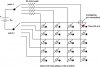
Hello. I am of need of a little assistance in trying to set up an LED array. Basically, I need to set up an array of LED's (4x5 array) in which I can control which 1 LED is lit up. I plan to use 20 red LED's (generic type, rated at about 2 Vf) run at about 20mA and two rotary switches to control the output.

For example, say if I wanted to light up the LED in the top left corner, we'll call it A1, then I would turn both of my switches to the corresponding row A, and column 1, or vice versa, and only that led would light up.

But I can't figure out what sort of power source to use, or what type of resistors (if any) I might need. Or how to wire it to my power source for the correct flow of current, since I'm using two switches.

Again, this is not an array I intend to hook up to microcontrollers, etc. in order to make dazzling patterns with programming. I only intend to light up one(1) LED at a time, in a coordinate system-like fashion. You could think of it almost like Battleship.

Any help would be much appreciated, and feel free to ask for any clarifications.
 
I'm currently making a similar circuit.

You need to use two input AND gates, 4081 CMOS ICs. One input of the AND gates connects to one of your rotary switches while their other inputs connects to the other rotary switch. You will also need to use "pull-down" resistors on each gate input (connected to ground.)

The way this works is that an LED will light when both inputs of your AND gates are high.
With a 4x5 matrix, use an AND gate for every row, you'll need five.

Hope this helps.
 
You don't need AND gates. The two rotary switches are all you need if you only want one LED lit at any given time. How long do you want the LED to be lit for? That is what you'll want to know in order to select an appropriate power source. Once you answer the question, I can post a schematic for you.

EDIT: Also, is the 4x5 array 4 columns and 5 rows or the other way around?
 
Last edited:
1. I will just have regular, standard Red LED's.
2. Well, lit as long as the two switches are matched to a corresponding LED. I won't have this running all the time (it's for a school project), but the LED's must be lit for as long as I have it powered (which would be about 10 minutes at the absolute most)

This will be a 4x5 with 4 columns and 5 rows.

Below is a sketch of the array or "grid". Each intersection represents 1 LED.
______
|_|_|_|
|_|_|_|
|_|_|_|
|_|_|_|
 
Last edited:
Here is a schematic showing how you can wire up the LEDs for them to operate how you've decribed. There are two rotary switches to select the column and row.

4x5 LED Array..PNG

Here are links to a few rotary switches that will work for your project.

5 position rotary switch: R20507RR02Q C&K Components Rotary Switches

4 position rotary switch: MR-14-A5 Well Buying Rotary Switches

The 5 position switch has more connections than you need but it will work for you and was actually cheaper than the version that only had the required number of connections.

For a power souce you can use 2 AA batteries in series. This will give you about 3V with fresh batteries. The LEDs will dim as the batteries are used up but they will remain plenty bright for most of the battery life. With normal alkaline batteries, you could run this thing for days before the batteries die.

Good luck with your project. Post back if you have anymore questions.
 
Last edited:
Dang, beat me to it vne147!

I was an idiot of my initial idea, it should have been more obvious to me...
 

Attachments

  • LED matrix switch&.jpg
    LED matrix switch&.jpg
    69.6 KB · Views: 225
Dang, beat me to it vne147!

I was an idiot of my initial idea, it should have been more obvious to me...

We pretty much came up with the same circuit except he only needs a single resistor wired between the common pin of the 5 position rotary switch and the negative terminal of the battery. Or instead, he could use a single resistor wired between the positive terminal of the battery and the common pin of the 4 position rotary switch. Six of one, half a dozen of the other.

Also, 50Ω is the correct caluclated value for 20 mA current, 3V supply voltage, and an LED forward voltage of 2V but I went with 47Ω becasue it's a more standard value and it will also allow the LEDs to stay brighter for a little longer as the battery voltage drops over the course of its life. The 47Ω resistor will allow about 21 mA current through the LEDs with fresh batteries but that will be just fine.

EDIT: Also, this is just a suggestion but for future reference if you place junctions at the overlapping wires that should connect, it won't be necessary for you to point out the overlapping wires that shouldn't connect. Like this:

4x5 LED array wit&#10.PNG
 
Last edited:
The updated attachment should work...
 

Attachments

  • LED matrix switch&.jpg
    LED matrix switch&.jpg
    69 KB · Views: 260
After looking at the data sheet for the 5 position rotary switch I originally recommended, I'm not sure that it will work. This switch:

MRY106-A-RO NKK Switches Rotary Switches

should work fine though. You could also use a SP4T and a SP5T slide switch in place of the rotary switches if you'd like.

Edit: BTW, I just noticed that you were in the Woodlands. I live in Clear Lake on the south east side. Mouser is just outside of Dallas and I order from them a lot. Becasue they are so close, I almost always get my order the next day even though I only pay for normal UPS ground shipping.
 
Last edited:
Thanks so much for your help guys! I just finished building the circuit and it works like a charm! The only thing left to do is to connect the wires from the array to the switches, and from the switches to the battery pack.

As a preliminary check, I went through and tested the LED's directly on the array, and they all power on just fine. But when I try to put power through each of the 10 foot wires leading to the array, I get no such result.

I'm using regular telephone wire, which is 6-conductor and stranded, and not getting anything to light up.

Any suggestions? I think I might need to move to a solid core.

P.S. Thanks a ton for the suggestions vne, I will check Mouser out.
 
Let me make sure I understand what you're doing. You are planning on seperating the batteries, resistor, and the switches from the LEDs by 10 ft. Is this correct? Like this:

4x5 LED array wit&#10.PNG

I wouldn't have expected the voltage drop along 20 ft of telephone wire to be large enough so that the LEDs wouldn't light. To check and see, measure the resistance of 10ft of the telephone wire. Check each conductor to see if the resistances are the same. Post back here with the measured value.
 
Your schematic is right on the money. And your right, neither did I. But give me a minute, and I will go find those values.

***Actually, nevermind. My multimeter just ran out of juice. But I can go ask one of the physics teachers to use one at school tomorrow and post the values sometime around lunch. (During my break of course)
 
Last edited:
Status
Not open for further replies.

New Articles From Microcontroller Tips

Back
Top