Continue to Site

Welcome to our site!

Electro Tech is an online community (with over 170,000 members) who enjoy talking about and building electronic circuits, projects and gadgets. To participate you need to register. Registration is free. Click here to register now.

  • Welcome to our site! Electro Tech is an online community (with over 170,000 members) who enjoy talking about and building electronic circuits, projects and gadgets. To participate you need to register. Registration is free. Click here to register now.

Learning About The 386 Audio Amp

Status
Not open for further replies.

Tucson Annie

New Member
Hi Guys,

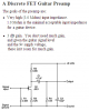
I'm playing around with a 386 chip, learning about what it does. I decided to follow a simple circuit layout in Forrest Mim's Timer, Op Amp & Optoelectronic Circuits and Projects book just to see the simple use of the chip. If anyone has the book, the circuit is on page 43 (I'd draw the circuit but I have yet to purchase any circuit sim software....off topic: has anyone ever heard of Circuit Shop by Cherrywood Systems? It looks easy and cheap **broken link removed**).

So, being a guitar player I decided to use my guitar as the signal source. I plugged it into a 10k pot the circuit design called for as a volume control and then the output was an 8 ohm speaker (after a 220uF cap). It worked, but the sound was weak....so, I figured it's because I believe passive guitar pickups have a high output impedance, so I put a 1 M ohm resistor on the input. I got nothing...no sound...so, I lowered the resistor value to 470 K and actually got a better sound than with just the 10k pot....so, I figure I am on the right track as far as input impedance goes.

The next step was to put a 10 uF cap between pins 1 and 8 at Forrest Mim's suggestion to crank up the gain....well, all I got was a bunch of nasty feedback noise....so I lowered that cap value to 1 uF and except for some crackles and pops, the gain was actually pretty good with just a little distortion of the guitar signal.

Then, I decided to get fancy and put this all in a box. Now, the noise is crazy bad and I'm guessing it is because the wires I used to put this all together in a little box are long (some over 6 inches) and they are picking up noise....my question after all of this is: Is that a reasonable assumption? My wiring is correct and even though I am not planning to use this as a practice amp, I'd like to know what's causing the noise....I figure today I will re-breadboard it with shorter wires and see if the problem goes away.

I'm rambling, lol...does this make sense? One last question: is there a way to check output impedance on a guitar pickup without opening up the guitar? I don't think it would be as easy as checking the resistance on the guitar cord ...I'm new to all this....I appreciate any input!

Annie :)
 
I use LM386 as a noise generator. Works great :)

At high gain conditions, it'll(long wires) pick up RF in addition to the built-in noise.
 
Without knowing about your curcuit, or guitar pick-ups, all I can say is that it's not possible to "solve" high signal impeadance with passive devices ( resistors, capacitors ) If that is in fact your problem, you need an impeadance transformer ( not an actualy transformer, but an active circuit with high input/low output impeadances ) You can implement someting such as a common collector amp, or a non-inverting opamp circuit.
 
Hi Guys,

Thanks for the input...I really appreciate it! I am truly a noob when it comes to actually making stuff and not just reading theory. :)

So, Transistor495, I take it this particular op amp is known for being noisy...lol...don't worry, I wasn't planning on actually using this circuit for anything in the real world, I just wanted to see how it worked....

And Brownout, as far as the impedance thing goes, I'm just trying to figure out what the 'standard' output impedance of a passive guitar pickup is....just for knowledge sake...I'm pretty sure that it is very high...I was just wondering if there was a way to bench test it.....

Thanks for the feedback!

Annie :)
 
There is a way to bench test it, but you need either a o-scope or a meter that works at the audio frequency. DMM's have very limited bandwidth, so I wouldn't try using one for this. You can make a simlpe meter with an opamp, diode, capacitor. I don't have a diagram,but if you want to try it, I can cobble something up. So, the idea is to connect the measurement instrument to your guitar, and use a variable resistance in parallel with the measurement device. adjust the resistor until the reading falls to 1/2 the value measured with zero resistance. That should be your output resistance.
 
Last edited:
Experts say that a guitar should drive a circuit that is at least 3M ohms.
The LM386 has an input impedance of 50k and the 10k volume control in parallel with it results in only 8.3k ohms. The output signal of a guitar will sound bad and will be reduced when it is shorted with only 8.3k ohms. Adding a resistor in series with the amplifier increases the impedance for the guitar to drive but reduces the level fed to the amplifier.

The LM386 has an output power into 8 ohms with a 9V supply of only 0.45W at clipping which is not loud. A cheap clock radio is louder.

Here is a preamp for a guitar. It has a 3M input impedance and not enough gain to be overloaded. It is shown with a 51k load but if the volume control at the input of the LM386 is raised to 100k ohms then the preamp can drive them.
 

Attachments

  • guitar preamp.PNG
    guitar preamp.PNG
    15.4 KB · Views: 968
You guys are great, thank you! Since my last post this is what I've done....and remember, this isn't for any real world guitar amp application, it's just me goofing around to see with my own eyes how these little op amp circuits work and what affects them....

I switched out the 10k pot with a 100k pot (hey, that's what Audioguru suggests, too!), took out the 470K series resistor, took off the 1 Uf cap for gain across pins 1 and 8 and except for the fact that it isn't loud at all and the continuous hissing, the tone of the guitar is pretty fat! I'm using a Daisy Rock semi-hollowbody guitar and it's rockin! Lol....if I could get rid of the hiss and try Audioguru's preamp to get some volume it MAY be suitable for real world practice, ha! I could make little practice amps for my guitar playing friends for less than 10 bucks, Merry Christmas! :p

Thanks guys,

Annie
 
You notice hiss from the LM386 amplifier maybe because your speaker is not accurate and is boosting the high frequency hiss frequencies.

The input impedance of the 100k pot and the 50k LM386 is a total of 33k ohms which is much too low and causes the output level from the guitar's pickup to be reduced.
You need the high input impedance preamp circuit.

Look at The Ruby Guitar Amplifier in Google. Ruby
 
I was afraid we were talking about megohms, in which case my prescribed method of bench measurement won't work. You'll have to take the input impeadance of your measurement instrument into account when making your measurements. Further, you'll have to use two different values of parallel impeadances, and solve the resultant simultaneous equations for the voltage dividers.
 
Last edited:
There are plenty of commercial portable guitar amps using just a LM386 and a 9v battery, and a few resistors/caps etc. And they are quite loud, and have plenty of gain without needing a preamp. Any typical magnetic guitar pickups put out 0.5v, many of the "rock" pickups will put out 1v to 2v signal.

**broken link removed**

good thread on the subject here;
LM386 based guitar amp
 
There is a big difference between the LM383 8W amp and the LM386 0.5W amp.
 
You guys are all great, I thank you all for all of the input! I've built the Ruby and the Little Gem practice amps from Runoffgroove.com and they both sound great! Once again my whole purpose of this little project was just to see at a minimum what makes soundwaves move through a passive pickup, down a wire, into an op amp and make noise on the other side....I just have this need to visualize how things work or I obsess about it forever, lol....

Eventually I want to build a tube amp for my guitar, but that's way down the road....first I need to understand where the signal is going....how to troubleshoot...where to put caps to filter out noise....all of the basics.

I'll post a picture of my project and a schematic later this weekend....

Thanks, all!

Annie :)
 
The LM386 is not an opamp. Instead it is a little power amp.
The max output current of an opamp is 20mA. The max current from an LM386 is about 400mA.
An opamp needs negative feedback to be added. An LM386 has built-in negative feedback.
An opamp needs its input biased. An LM386 has input biasing built-in.

A capacitor that filters out noise also filters out important high audio frequencies.
 
Status
Not open for further replies.

Latest threads

New Articles From Microcontroller Tips

Back
Top