Hello everyone,
Recently I began fixing up a neighbors lawn mower. It runs but I can not quite wrap my head around the flow of current withing the ignition/spark system.
I know the following:
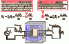
The system consists of a magnet located on the flywheel.
The magnet spins around and induces a current on a coil.
The coil then ups the voltage by going to the secondary winding just like a transformer.
The current from the transformer flows into the spark plug past a very small air gap and to ground on the mowers engine block.
Now knowing the above gave me knowledge to fix it, but I am having some real trouble visualizing the flow of current in this system, the many grounds of the engine, spark plugs, and transformer are confusing me.
Confusing parts are mainly;
current flow,
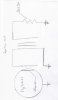
What the proper circuit diagram is
how all the grounds such as screws on the coil work
Why is the secondary circuit ( spark plug, to engine block) grounded why wouldn't it just work like a 'normal transformer' circuit a shown in the picture
Below is some attached images that may help.
Thanks!
Recently I began fixing up a neighbors lawn mower. It runs but I can not quite wrap my head around the flow of current withing the ignition/spark system.
I know the following:
The system consists of a magnet located on the flywheel.
The magnet spins around and induces a current on a coil.
The coil then ups the voltage by going to the secondary winding just like a transformer.
The current from the transformer flows into the spark plug past a very small air gap and to ground on the mowers engine block.
Now knowing the above gave me knowledge to fix it, but I am having some real trouble visualizing the flow of current in this system, the many grounds of the engine, spark plugs, and transformer are confusing me.
Confusing parts are mainly;
current flow,
What the proper circuit diagram is
how all the grounds such as screws on the coil work
Why is the secondary circuit ( spark plug, to engine block) grounded why wouldn't it just work like a 'normal transformer' circuit a shown in the picture
Below is some attached images that may help.
Thanks!