Continue to Site

Welcome to our site!

Electro Tech is an online community (with over 170,000 members) who enjoy talking about and building electronic circuits, projects and gadgets. To participate you need to register. Registration is free. Click here to register now.

  • Welcome to our site! Electro Tech is an online community (with over 170,000 members) who enjoy talking about and building electronic circuits, projects and gadgets. To participate you need to register. Registration is free. Click here to register now.

Latching a comparator ?

Status
Not open for further replies.

ItsMike

New Member
Hey everyone,

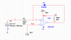
I have a 0-5v+ signal (from a non inverting op amp) going into a comparator with a vref of about 5v from a 5.1v zener.

I want the comparator to latch up when the input signal goes over 5v and keep latched until the circuit is powered off.

I figured I would need some kind of positive feedback but i'm really rusty with that.

Btw the comparator has an open collector output (lm239).

Thanks in advance.
 
You add a diode from the output to the plus (+) input which will keep the plus input above the value of the minus input 5V reference after the output goes high, even when the input goes to zero. See the example circuit below.

Comparator.jpg
 
Now i'm even more confused.

I made the circuit, except that I used a 28v power source to feed the comparator.
I'm trying to figure out why the output is at 3v before the latching.

What should I change, add to get logic level outputs ?
 

Attachments

  • Capture.PNG
    Capture.PNG
    13.1 KB · Views: 1,158
  • 2.PNG
    2.PNG
    13.6 KB · Views: 720
I simulated your circuit with Electronic Workbench (below) and it looks fine.

Your LM239M model may have a problem. Where did you get it? If you are using LTspice, attach your .asc file (with any added models) and I'll try to simulate it.

Comparator.jpg
 
I get a similar result in ltspice too.

I use the lm339 model from the yahoo group.

EDIT:
I managed to get a good graph by adding a resistor in series to the diode, it was just trail and error.
The simulation is unstable though, if i change R3 to 9k instead of 10k the circuit doesn't work properly.
What the hell is going on ?
(New file uploaded, "Comparator_new")
 

Attachments

  • comparator.asc
    1.4 KB · Views: 283
  • comparator_new.asc
    1.8 KB · Views: 259
Last edited:
The circuit in post #3 applies a current limited +28 V back to the 5 V input signal source. Don't know if this is a problem, just pointing it out.

If it is, you can add one transistor or another 239 stage to have the main comparator manipulate its reference input for the latching hysteresis instead of the signal input.

ak
 
The Zener shows odd behavior. The simulation in Step DC, Start external DC Voltages at zero shows an result for the simulation. A resistor devider of similar voltage at the inverting reference shows operation without the need for Zero volt DC startup in simulation command .Tran

All tho thoughts with an Zener, the Inverting inputs stage may not have anywhere to place current resulting in an floored input (forward biased). Are those not PNP types?
:For some reason my Sim would not open the library file for the LM339:
 
Status
Not open for further replies.

New Articles From Microcontroller Tips

Back
Top