Continue to Site

Welcome to our site!

Electro Tech is an online community (with over 170,000 members) who enjoy talking about and building electronic circuits, projects and gadgets. To participate you need to register. Registration is free. Click here to register now.

  • Welcome to our site! Electro Tech is an online community (with over 170,000 members) who enjoy talking about and building electronic circuits, projects and gadgets. To participate you need to register. Registration is free. Click here to register now.

L297 Stepper motor driver

Status
Not open for further replies.
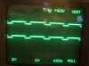
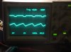
I never attached a scope on 297 output .. but I imagine if you clock it manually and look at output step by step ... 297 don't do micro stepping so the signal should be clear .. might be easier to debug the output if you use full step and not half step settings.

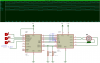
you can use a 3pin switch to clock manually outter pins to vcc and gnd, middle pin to clock pin on 297 :)
 
Thanks again, arhi:)

I will play with this a bit more tonight and post back with my results.

So the CLOCK needs to go HIGH/LOW and not HIGH/FLOAT or LOW/FLOAT? Is that correct?

Step clock. An active low pulse on this input advances the motor
one increment. The step occurs on the rising edge of this signal.

Could I use a resistor to pull the CLOCK pin high and a momentary push button to ground it? Would that also advance it?
 
Just an update.

I got my scope out and put it on the output pins of the L297. The outputs all go HIGH and LOW. I have a 2 channel scope, but can't locate my other probe..... so I can't see how the outputs look side by side.

They outputs don't look too clean. I was kind of puzzled by this, but then realized I am using a 5v wall wart for my 5v supply. It holds right at 5 volts with a small load, and I have powered PICs with it with no trouble. I put the scope on that and I have a crummy sawtooth wave. That can't be helping anything. :eek:

I'll have to take some time and redo it with a 7805 or atleast add a good filter capacitor to the wallwart to rule that out as a problem. I am too tired tonight.:(
 
one hint, while debugging, be sure not to use same power line for pic and for motor (pin4 on 298) ... when you are sure it all works, then if needed to power them from same line add filters etc .. but initially - be sure to split them, might save you few nights.

also, if you are clocking manually you can check output one by one, do not check only A/B check also the enable pin.
 
Okay, here is what I have.

The L297 is connected as arhi outlined. I have tried -

FULL and HALF step

CW and CCW

CONTROL both HIGH and LOW.

Power is now supplied by a 7805 run off a 9v battery.

CLOCK is supplied by a 555 running very slow.

I found my other probe so I can look at 2 outputs at once. They all follow the 555. It dosn't matter how I connect the probes. The trace in the picture below is what I get.

Picture number 2 is one output against the 555 output. I don't know why my 555 has such a strange wave. I have 100µf cap on it. Bigger then is normally used I think. Maybe thats why:confused:

I am a novice with my scope, but it dosn't look to me like the 297 output travels the full 0-5v.

I did order 2 of these chips. I tried both and they do the same thing.

I didn't know this was going to be a week long project. :rolleyes::D
 

Attachments

  • scope.JPG
    scope.JPG
    194.5 KB · Views: 269
  • 555 scope.JPG
    555 scope.JPG
    187.2 KB · Views: 239
Last edited:
hi Andy,

Power is now supplied by a 7805 run off a 9v battery.

If you are powering the full system, ie PIC, LM297 and the motor from a 9Vbty,
its most likely that the 9V PP3 isnt up to supplying the current required.

You require a psu for the LM297/motor than can supply at least 2A to 3A at the required motor voltage.
Keep the PIC powered from the 9Vbty and 7805 while testing.
 
Last edited:
the pic1, thats output from what 2 pins of 297?
I don't recall, but I tried all the outputs and could't get a change.


Eric, right now all the 9v is powering is a 555 timer, small led to give me a visual indicator the 555 is running and the L297. I back off with the 298 and the actual motor until I can be pretty sure I have the 297 working.
 
andy, strange ... if that's 4 and 7 then ok but if that is 4 and 6 for e.g. that;s problematic

if your scope features different ground for 2 probes you can connect

probe1 gnd to 4, tip to 6
probe2 gnd to 7, tip to 9

if not then connect probe1/2 ground to 2 and tips to 4 and 7 and then let it "clock"
 
I will try that tonight. I kind of doubt its the chip, so it must be some dumb mistake I am making. This sure is proving alot harder then it looked.

I guess the only bright side is you don't get a chance to learn much when things just "work" on the first try.

I had a few minutes before I left for work thismorning, and I connected a 12v 3 amp power supply to the 7805. The 555 still has the goofy wave to it. I wouldn't think that would be the problem, but it sure has me wondering.....
 
here's the working simulation:

you have the 5 sec worth of data in the "digital analysis" for 1Hz clock

EDIT: here's the avi ... (sorry was not able to convert it to anim gif)
 

Attachments

  • stepper.png
    stepper.png
    22.2 KB · Views: 592
  • steper.avi.zip
    691.4 KB · Views: 210
Last edited:
Hi,

I think that the 7805 needs capacitors. Otherwise it act strangely.

I would have a question. In the datasheet of the L298, page 8 they suggest to use 2A fast diodes types. What would be the least expensive diode for that purpose?
 

Attachments

  • 7805 capacitors.jpg
    7805 capacitors.jpg
    15 KB · Views: 417
Last edited:
:eek: I deserve a darwin award........

I had small ceramic caps on the 7805, but didn't have anything else for capacitors on the power supply.

After spending an hour trying every conceveable combination of the CONTROL/INH1/INH2 to get a output like arhi's simulation I grabbed this big ole' 10000 uF cap that was rolling around on my bench and stuck it across the power rails. Ta da. Output now looks like arhi's simulation.

live and learn I guess. Working on hooking the L298 back up now.....

Now the 555 has a nice clean square output too.
 
Last edited:
Its working!!!!! lol

Thank you so much for all the help, arhi! And thank you, AlainB for suggesting the caps on the 7805, and thanks to everyone else that responded.

:D:D:D:D:D
 
Status
Not open for further replies.

Latest threads

New Articles From Microcontroller Tips

Back
Top