Hello,
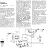
I built the attached schematic. I found that it is working, the minimum output voltage is around 2.8V, the maximum is around 20V. The minimum current is 0.25A and the maximum current is 1.6A. I used an 15Vac/2A transformer and a 4A bridge rectifier. I was wondering why the output voltage and current is not falling down to 0V, and I found that the voltage on the 5v6 Zener is about 0.4-0.5V. I disconnected the GND for 741 and for L200, and I found that the voltage on the zener raised to about 4.1V. I replaced the zener with a new one, and the same thing happened again. I also tried with a new L200, but the same thing happened again.
I can't find the problem, can someone please help me with some advices ?
Attachments
Last edited:
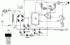
") The voltage regulation characteristics are bearable. At my breadboard build there is a shift of 0,3V when loaded with 400mA. But that must not mean anything to a proper build PCB circuit.
The voltage regulation characteristics are bearable. At my breadboard build there is a shift of 0,3V when loaded with 400mA. But that must not mean anything to a proper build PCB circuit.