Continue to Site

Welcome to our site!

Electro Tech is an online community (with over 170,000 members) who enjoy talking about and building electronic circuits, projects and gadgets. To participate you need to register. Registration is free. Click here to register now.

  • Welcome to our site! Electro Tech is an online community (with over 170,000 members) who enjoy talking about and building electronic circuits, projects and gadgets. To participate you need to register. Registration is free. Click here to register now.

Klarstein thermoelectric mini fridge suddenly stopped cooling.

Status
Not open for further replies.

sdagger

New Member
Hi

I wonder if anybody has further knowledge or can help me with my query on how to fix my mini fridge which has suddenly stopped cooling. Rather than re-write my issue posted elsewhere, it would be fantastic if somebody closer to the UK could help. I'm happy to post the circuit board if need be.

My problem is all explained in the do it yourself website below:

https://www.doityourself.com/forum/...ermoelectric-mini-fridge-stopped-cooling.html

Anything that could help me would be amazing.
 
I think they are wrong. The label clearly states "thermoelectric refridgerator".

As for the coolant;
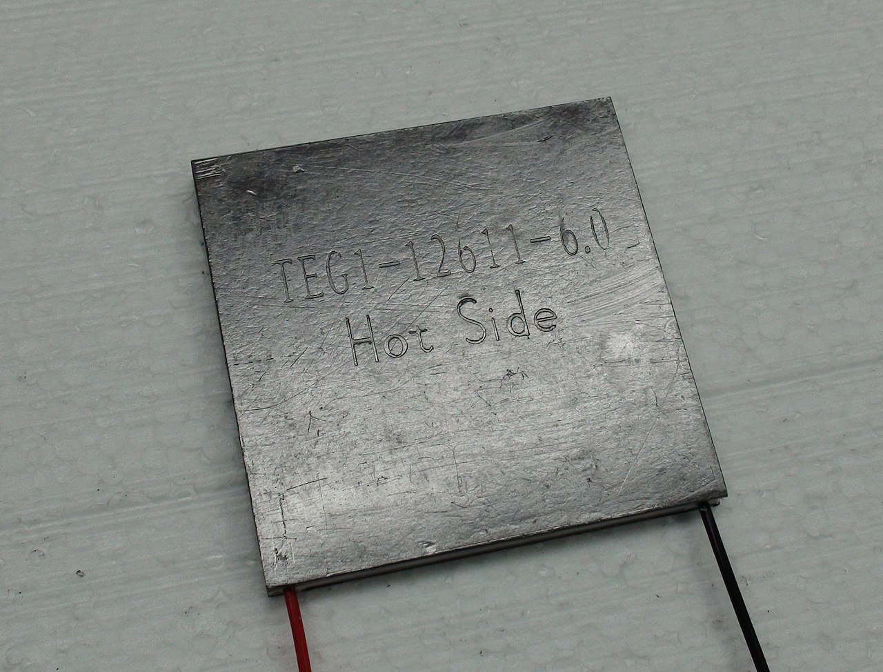
1280px-Thermoelectric_Seebeck_power_module.jpg
a peltier heat pumps still need the cold side kept cold. The coolant in in the large diameter black tubes and circulates via convection.
The thin wires connecting the loops of tube together form a radiator and that's what the fans are blowing over.

The absence of one fan should not stop the fridge from getting cold; only stop it from getting as cold as it should.

Can you feel any heat in the pipes as they enter/leave the big black box with the white blobs on top?
If not, it is probably the heat pump that is open circuit.

Trace the pair of wires eminating from that box back to the board and use your meter to test for open circuit or resistance.
 
Hi. You lost me a bit. The black box with the jelly looking bolt caps? Not sure what you mean about heat pump open circuit? I'm a novice sorry.

If you could tell me what settings on multimedia to use and what to look for that would be great.
 
This photo on the other site appears to show the 12V wires for the peltier unit - and it looks like the solder joints are broken, as if they have pushed through the board and broken the PCB traces?? They just look really nasty..

fridge.jpg
 
Hi. You lost me a bit. The black box with the jelly looking bolt caps? Not sure what you mean about heat pump open circuit? I'm a novice sorry.

If you could tell me what settings on multimedia to use and what to look for that would be great.

Sorry. I don't know anything about multimedia settings.
 
I think the OP probably means multimeter rather than multimedia.
I think the this theory ( I never considered that. A Peltier chip doing the cooling but instead of the usual big aluminum heat sink they could be using a heat pipe system. ) suggested in post #6 of the tread on the other forum is correct. The black area where the two ends of the heat pipe go through the back of the fridge is the hot side of the Peltier device. If there is power getting to it (And it is not faulty.) when it is set to cool that area should start to warm up. I suggest that you check if that is happening and report the results.

Check the solder connections mentioned in post #4 of this thread and measure the voltage between them when the fridge should be cooling. Set your multimeter to the 20 volt DC range. (I am guessing the voltage will be about 12 volts.) If you get an over range indication switch to the 200 volt DC range.

Les.
 
Last edited:
  • Like
Reactions: Buk
Hi. In Answer to Les Jones, I checked the area after 20 mins of fridge powered on and do not feeling any warming in the black area. I also checked the solder area and is still in factory condition, nothing loose for example. As my post in previous site, I set multimeter to 20 volt DC but don't see any volts at all but i'm sure i'm using multimeter correctly. Is there anything else I could check on the PCB or is it all just goosed? Fans all spin, lights work, fans stop when door opened so all normal except no cooling.
 
I checked the area after 20 mins of fridge powered on and do not feeling any warming in the black area.

Two possibilities:

1) the Peltier unit -- the thing that is connected to the red & black wires that disappear inside the large black box -- is broken and would need replacing.

If this is the case, repair would require opening that black box up to allow the Peltier unit to be replaced; but that would almost certainly mean messing -- containing, replacing, re-sealing -- the liquid refrigerant. And that would require very specialist skills.

2) one or more of the components on the circuit board is broken and thus the circuit is not providing any power to the Peltier unit.

If it is the circuit board, there is a possibility of working out which components are bad and replacing them, but given...

As my post in previous site, I set multimeter to 20 volt DC but don't see any volts at all but i'm sure i'm using multimeter correctly.

it would be an exercise in frustration for anyone to try to talk you though how to check the components; let alone sourcing and fitting replacements, and in the end, it might still not work.

You'd really be better to try and get it serviced by the manufacturer; or someone like an A/C engineer.
 
Last edited:
A drawing showing where a;; the wires from the PCB go would be helpful with the connector numbers on the PCB end of the wires and the name of the item the other end. ( For example. Thermostat, fan (With it's location). Also a picture of the PCB with the wires weld so they don't obscure the view of components on the board. A good picture of the etch side of the board would give a better idea if the tracks to the Peltier device connections were damaged.
I was wandering if the thermostat was a normal type of fridge thermostat or a thermistor and thermostat control was just a potentiometer.
As the Peltier device takes quite a high current I think it will be a normal thermostat with switching contacts. If it was a thermistor I would expect to see a relay or power transistor on the board.

Les.
 
Hi. would this help any?


"Strange, I have answered the question before.
The second fan only runs when the cooling unit is active. "
1628455990299.png

" Is the temperature regulator in working order? "

I wouldn't know where to look.
 
Hi Buk, I had noticed the NTC marking on one of the connectors which would suggest an electronic thermostat. I have never played with Peltier devices but my understanding is that they require quite a high current. This is why I had a look at the PCB to see if there were any devices that looked capable of switching a high current. I have asked sdagger to do a drawing showing all the wires from the PCB and their destination. This might help. I have just noticed that there are two transformers on the PCB so there could be two switch mode power supplies. One low power one that runs all the time and a higher power one that just provides power to the Peltier device. I have also requested a picture of the etch side of the PCB and this may help us to decide how the temperature is controlled. If the temperature control was easy to take apart it would be interesting to see if it was just a potentiometer or a normal type of fridge thermostat.
I don't think it would be safe too get sdagger to do any testing on the primary side of the power supply.

Les.
 
Les,

My limited knowledge of Peltier devices come from having to sit through a bunch tender proposals for heating/cooling solution for remote servers. I was a system architect on a networking project for the cargo branch of a european airline. The project involved installing and remotely maintaining a server at each cargo destination across EMEA. Several of the servers at the smaller, more remote airfields where installed in what were little more than corrugated iron shacks, which meant they could either get very hot in summer or very cold in winter. The chosen solution was a peltier device as it could serve both purposes .

The heat tube ran from the server enclosure down to a large aluminium plate buried a few feet under ground where it was colder than ambient in summer and warmer in winter. That system used a thermister. I don't know any more details.

But a word of caution: There is discussion (in the otther forum) of undoing the silicon sealed bolts shown left and right in this image:
1628532790596.png


I believe the 3rd central silicone cover labelled with a ? above, is the valve used to inject the refrigarent into the system under pressure (to make it liquid), and the silicone seals are there to prevent leaks. If the bolts are undone, the liquid will escape as gas.

My gut tells me that it is the board that is at fault, and the peltier unit and cooling matix should be left well alone. Besides the gas leak problem, peltier devices are famously physically fragile.

Perhaps the simplest way to check the peltier device would be to use a 12V battery (car, bike) to drive the PD direct and see if a differential temperature develops between the input and output pipes. However, I don't know enough about PDs to know if they require a current limit supply.
 
The fact that sdagger did not get a voltage reading on the PCB end of the wires to the Peltier device suggests the fault is not the Peltier device. I think if the liquid in the heat pipe had to be released it would cost too much to find someone that that could re fill it. Out of interest I had a look at the properties of cyclopentane and it' boiling point is 49 Deg.C. So I think the heat pipe is filled at a pressure below atmospheric so it boils at less than 49 degrees. I think the hot side would need to be at a lower temperature than 49 Deg. C

Les.
 
. Out of interest I had a look at the properties of cyclopentane and it' boiling point is 49 Deg.C.

I don't know any better, but according to wikipedia R134a has " a boiling point of −26.3 °C (−15.34 °F) at atmospheric pressure. "; hence my belief that the system has to be above atmospheric pressure.

Also, the label lists the cyclopentane as "foaming gas"; which I take to mean that it is a "co-current liquid". And now I'm simply quoting stuff that I have no first hand knowledge of and barely understand :)
 
Last edited:
Or...the Peltier device is short circuit?

I can't say I'm familiar with peltier devices, are you?, and is that a common failure mode? - otherwise it's VERY, VERY unlikely - and odd devices going S/C is mainly a theoretical idea, almost always with no chance in reality.

Certain devices do go S/C, but there's many more which never really do, as their construction doesn't lend itself to that type of failure.
 
Certain devices do go S/C, but there's many more which never really do, as their construction doesn't lend itself to that type of failure.

You did notice the question mark at the end of my question? <<<< Like that one.

From a peltier unit manufacturer's FAQ.

As the assembly is thermally cycled, not only does the module itself undergo fatigue stress, the bond line between the module and heat sink is also stressed. Again, different materials will expand at different rates. The heat sink, the solder (or epoxy), and the module will expand differently. This can be particularly troublesome because the bond could potentially fail at local spots. The module could overheat at these local spots which would exacerbate the problem. This is why we do not recommend soldering (or epoxy-ing) the module to its heat sink. If you do solder (or epoxy) the modules, we recommend that you thermal cycle the compete assembly to make sure you get adequate lifetimes.

And later:

The temperature ratings for the modules are derived from their construction technique. The 80 °C module uses solder that melts at 140 °C. It has excellent electrical contacts. The 200 °C module also has two nickel barriers: a layer of nickel on the copper tab and a layer of nickel on the ends of the pellet. The solder melts at 232 °C.

Given the mechanical construction:
1628580430468.png

If the unit overheated -- because say, one of its fans died -- is it such a stretch to imagine the possibility of the solder connecting the pellets to the copper plates top and bottom might bridge the gap?

The simplest check would be to test the resistance as I first suggested in post #2.
 
Last edited:
Hi Buk, I had wrongly assumed that cyclopentane was the chemical name for the R134a refrigerant and "foaming gas" was a description of it' properties.
You post #18 corrects another wrong assumption I had about Peltier devices. I had thought that the device consisted of a number of junctions in series (Both electrically and thermally.) so there was only a small temperature difference across each junction. With this wrong reasoning I thought it was unlikely that all the junctions had failed short circuit. Looking at the diagram In see that in the past I had wrongly thought about Peltier devices working in a similar way to thermocouples in reverse.

Les.
 
  • Like
Reactions: Buk
I had thought that the device consisted of a number of junctions in series (Both electrically and thermally.)

I'm not sure that description is far wrong. The best actual image I found of one that shows the construction is this:
1628588326442.png

Which isn't great, but probably means the possibility of total short circuit is pretty remote.
(But I only just found this.)
 
Status
Not open for further replies.

Latest threads

New Articles From Microcontroller Tips

Back
Top