throbscottle
Well-Known Member
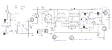
I've been having nice success using a IR21531S as a speed control for a 24vdc motor which draws around 3A running and over 10A startup. A time-switched resistor limits the start current (3R3 for about 200mS, then 0R1 to feed a tacho in the future). The motor is the spindle motor for my PCB drill, finally moving from perf-board prototype to a proper board. The high and low side transistors are FDP047AN08A0 (75V, 80A, 4.7mOhm)
I've been running it from an old wall-wart with the speed turned down, for testing, and it's worked very well. Since today is the day I was going to use the prototype to drill the PCB which will replace it, I connected an unregulated supply consisting of transformer, rectifier and 3300uF capacitor (just what I happened to have lying around), 27v no-load, so it can run at full speed.
But what actually happened was that the high side transistor blew s/c, apparently at switch on. The only thing that was different was I'd missed off the on/off control connection to the IR21531S after previous tinkering, so it went straight to "on" instead of starting up in shutdown, but I don't really see why this would have caused the failure.
So can anyone suggest what might have actually happened at switch-on, here?
As always, thanks in advance")
I've been running it from an old wall-wart with the speed turned down, for testing, and it's worked very well. Since today is the day I was going to use the prototype to drill the PCB which will replace it, I connected an unregulated supply consisting of transformer, rectifier and 3300uF capacitor (just what I happened to have lying around), 27v no-load, so it can run at full speed.
But what actually happened was that the high side transistor blew s/c, apparently at switch on. The only thing that was different was I'd missed off the on/off control connection to the IR21531S after previous tinkering, so it went straight to "on" instead of starting up in shutdown, but I don't really see why this would have caused the failure.
So can anyone suggest what might have actually happened at switch-on, here?
As always, thanks in advance