Continue to Site

Welcome to our site!

Electro Tech is an online community (with over 170,000 members) who enjoy talking about and building electronic circuits, projects and gadgets. To participate you need to register. Registration is free. Click here to register now.

  • Welcome to our site! Electro Tech is an online community (with over 170,000 members) who enjoy talking about and building electronic circuits, projects and gadgets. To participate you need to register. Registration is free. Click here to register now.

Kickback diode for a small DC motor.

Status
Not open for further replies.
1N4001 is good for 50 volts. You motor is 7 or 12 volt. :) (happy face)
1N4001 is good for 1 amp all day long. 45A for 1mS, 30A for 5mS
I do not know how the Arduino is controlling the motor.
When you turn off the motor the kick back will be for a short time.
BUT: you might be using the diode as a brake. I think current will flow in the diode while the motor is running down.
Which motor are you using 7V or 12V? I see the current is very different.
At no load the current is so low it does not matter.
At maximum efficiency the current is 1.76 A or 0.14A. I think the diode will hold for 1 second at 1.76A. :) I think the 1.76A will quickly run down to a very small number.
At stall the current is 8A or 0.4A. (????) There will be the 8A kick back for a very short time. But at stall there will be no generator effect where the load causes the motor to turn. :)

Some one who knows more about motors should help! But I think the 1N4001 is good.
 
BUT: you might be using the diode as a brake. I think current will flow in the diode while the motor is running down.
It doesn't work like that. Assuming that the motor only runs in one direction, when the current is interrupted, there is a brief negative voltage across the motor, due to the inductance of the windings. That is what the diode will suppress. Then while the inertia of the motor and the load keep the motor turning for a bit until friction etc eventually stop it, the voltage across the motor will be positive, gradually reducing to zero as the motor slows. The diode will not be conducting, so will not contribute to motor braking.
 
I do not know how the Arduino is controlling the motor.
Yes, this info would be helpful, H-bridge or just fet/transistor controlled by PWM via arduino, or just relay rough on/off, for example.
1n4007 or similar would be enough, like nigel too said.
As for couple suggestions for control:
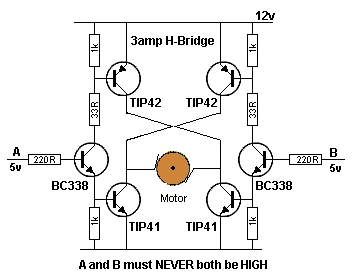
If you need two-directions, you need more that one diode, here's one variation for H-bridge, with benefit that there is no situation to kill drivers due bad control sequence (well okay, if a&b are both high..., that kills stuff):
3AmpH-Bridge.gif

And then there are these which has most things covered in terms of control and such, but that l298 driver can still die if things go sour(argh, why they took photo with bent pin?? I wouldn't buy car with empty tire hehe....):
 
Hy Fezder,

Just put four 1n400x rectifier diodes in the bridge: anode to PNP transistor collectors and cathode to positive supply line and cathode to NPN transistor collectors and anode to the zero volts supply line.

spec
 
Just put four 1n400x rectifier diodes in the bridge: anode to PNP transistor collectors and cathode to positive supply line and cathode to NPN transistor collectors and anode to the zero volts supply line.
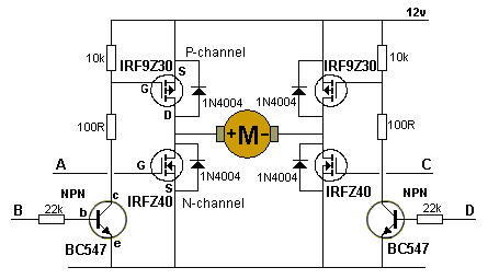
Oops forgot those, like this fashion?
H-Bridge-MOSFETs.gif
 
Hy Fezder

Thought you had missed the diodes in the case of bipolar junction transistor bridge but in the bridge circuit above the diodes are not necessary because the MOSFETs already have parasitic diodes with a current capability comparable to the drain current of the MOSFET.
images

spec
 
One method used on a small motor such as this if dynamic braking is needed at switch off is to turn ON both the bottom Mosfets.
Max.
 
Thought you had missed the diodes in the case of bipolar junction transistor bridge but in the bridge circuit above the diodes are not necessary because the MOSFETs already have parasitic diodes with a current capability comparable to the drain current of the MOSFET.
True, I was just lazy to look for BJT :p and maybe they forget those diodes from fets hehe...
 
To answer your question in one, Yes.
 
True, I was just lazy to look for BJT :p and maybe they forget those diodes from fets hehe...

The body diode in a mosfet is a parasitic part of the structure. It is not an added element.

I often wish I could get a mosfet without the body diode.
 
I often wish I could get a mosfet without the body diode.

Yes, that would be great but often the reverse parasitic diode is useful.

I expect you know that you can make a reverse blocking MOSFET by connecting two MOSFETS in series.

spec
 
Yes, that would be great but often the reverse parasitic diode is useful.

I expect you know that you can make a reverse blocking MOSFET by connecting two MOSFETS in series.

spec

Yes, I know that. I do a lot of DC power switching with mosfets. But it would be nice to be able to do it with just one mosfet, instead of two.
 
Status
Not open for further replies.

Latest threads

New Articles From Microcontroller Tips

Back
Top