Continue to Site

Welcome to our site!

Electro Tech is an online community (with over 170,000 members) who enjoy talking about and building electronic circuits, projects and gadgets. To participate you need to register. Registration is free. Click here to register now.

  • Welcome to our site! Electro Tech is an online community (with over 170,000 members) who enjoy talking about and building electronic circuits, projects and gadgets. To participate you need to register. Registration is free. Click here to register now.

Kenwood CS-6040 6040 Oscilloscope: Variable vertical control fault and HIC module

Steve Rawllings

New Member
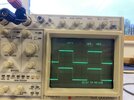
I have a Kenwood CS-6040 oscilloscope with a similar fault to that described by 'fezder' at:

As the previous thread has been closed, I've started this one.

In my 'scope, neither the variable 'HIC' attenuator module for Channel 1, nor the HIC module for Channel 2 responds to the variable gain control voltage derived from their respective front panel controls. Although the calibration of Channel 1 is unaffected, Channel 2 is only reading about one seventh of the true VOLTS/DIV.

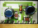
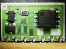
For now, I'm assuming that the HIC module has failed in a convenient manner for Channel 1, but the corresponding HIC has failed in a 'lossy' manner in the Channel 2 vertical amplifier.

Before I remove the HICs from the PCB, I'd appreciate any comments from others who have experience of these HIC modules, especially regarding possible alternative modules, or suitable home made attenuators.

Regards to all
Steve
 
Removing the two non-working HIC modules was quite easy. But I needed to make a tool for removing the 7-pin modules from the PCB. The pins of the module were quite tight in the PTHs, and a solder pump wasn't removing enough solder. I needed to make something that would heat all the pins at once.

I started with a 15 mm copper T piece from my plumbing spares, which I modified using a hacksaw and file so that it would fit on my large 700 degree Weller soldering iron bit. Removal of the two HIC modules was an easy task using this home made de-soldering tool!

I then replaced the PCB and was delighted that the correct vertical gain had been restored to Channel 2! And Channel 1, which would occasionally flicker, was now stable.

It's clear that the HIC attenuator modules really let down an otherwise superb 'scope. Removing them at the first sign of trouble is probably the best thing to do. Happily, most tasks do not require variable vertical gain.

Regards to all,
Steve
 

Attachments

  • Img_4038.jpg
    Img_4038.jpg
    114.9 KB · Views: 198
  • Img_4039.jpg
    Img_4039.jpg
    111.9 KB · Views: 190
  • Img_4061.jpg
    Img_4061.jpg
    138.7 KB · Views: 205
  • HIC.jpg
    HIC.jpg
    339.2 KB · Views: 195
  • Img_4062.jpg
    Img_4062.jpg
    108.8 KB · Views: 188
Those types of modules (not just in scopes) have always been pretty unreliable, you used to get them failing in TV's and VCR's etc. - either technology moved on, or the manufacturers realised they were unreliable, as they faded out of use.

BTW, do you always use your scope upside down? :D
 
I think it's an Australian scope Nigel :cool:
 
The tweaky pots for the vertical amplifier are on the underside. Adjustments were easy to make when following the procedure in the manual.

I’m waiting for a new clock battery to arrive and then I’ll be putting the covers on. A couple of weeks ago, only Ch 3 was working. Now it’s a four channel scope again. Happy days.

Thanks for the information, Nigel, about the HIC and similar custom modules. I’m glad that such custom modules weren’t used in more critical areas of this model of oscilloscope.
As an engineer I found them REALLY annoying, it's not like there's a great deal on them, yet they are such a specialised item that they rapidly become obsolete.
 
I would like to record my grateful thanks to Fezder for his original post about the CS-6040 and the unreliable HIC modules.

Fezder’s investigative work, and his clearly recorded fault history, saved me a lot of time.
 
Thanks much for posting this info about the 6040 vertical attenuation issue. I got a 6040 and it had the same issue on ch1, so I bought a cheap 6030 hoping it would have part HIC to swap out. The 6030 (100Mhz) came in excellent cosmetic condition and it actually worked fine, so decided to swap the entire board into the 6040 and it did seem to work fine. However, the board number had suffix 00 inked out and replaced with 01 so not sure if it was identical. So off to Ebay and got another 6040 dirt cheap and sure enough it had the same attenuation problem on ch1. So took the one good HIC from that and put in into the other 6040 and now it works OK. Ended up with a good 6040 , a good 6030 , and a 6040 with both CH1 and 2 without variable vertical.

Now have 2 bad HIC out of circuit to try to get the film off to figure out what it is. Maybe one of the 2 capacitors on it are bad, if that is what they are. May be some leakage at the bottom of them, not sure. Might be possible to replace them. I have depoted some other devices using boiling water but those were in solid chunks of epoxy that could be gouged out after it got soft. Did I read you used acetone to read a part number on the HIC?

Thanks again for taking the time to post this, without it I would have been stumped.
 
Last edited:
Here are pics of both sides of the HIC U102 KMC03 board, looks like a dual op amp jrc4558(LM741), a three terminal and a 4 terminal device both with no real markings. Since components are on both sides drawing out a schematic is a little harder. Just in case anyone has any info how to help identify the 3 and 4 terminal devices, or what they most likely are. Thanks to all.
 

Attachments

  • Kenwood 6040 HIC Atteruator Board Side 1.JPG
    Kenwood 6040 HIC Atteruator Board Side 1.JPG
    820.2 KB · Views: 111
  • Kenwood HIC Attenuator Board Side 2.JPG
    Kenwood HIC Attenuator Board Side 2.JPG
    819.4 KB · Views: 106

Latest threads

New Articles From Microcontroller Tips

Back
Top