Continue to Site

Welcome to our site!

Electro Tech is an online community (with over 170,000 members) who enjoy talking about and building electronic circuits, projects and gadgets. To participate you need to register. Registration is free. Click here to register now.

  • Welcome to our site! Electro Tech is an online community (with over 170,000 members) who enjoy talking about and building electronic circuits, projects and gadgets. To participate you need to register. Registration is free. Click here to register now.

keep relay on longer what capacitor?

Status
Not open for further replies.

smilem

Member
Hi, I have 5V relay that receives very short burst of power, to eliminate false positives I would like that my relay would be on longer. What size electrolytic capacitor I need to use? Do I need to use diode to protect my circuit from the capacitor current backflow?

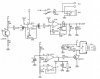
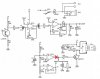
I use relay in this circuit instead of buzzer:
https://www.velleman.eu/downloads/files/schema/receiver.jpg

I added resistor to make 5V instead of 9V for the relay.
 
When does the relay receive the "short burst of power"? On power up? When the "beam" is broken? Don't know exactly which kit this is.
EDIT: Ahh. This is it; **broken link removed**
What you probably need to do is shield the phototransistor from ambient light. A black tube placed over it and facing the sender would help reduce false triggering.
 
Last edited:
Hi,

charging a capacitor from the output of a (?CMOS) device is proably not sufficient.

Better charge the capacitor after rectification of the output signal of the buzzer circuit and use a transistor to switch the relay.

I simulated the buzzer circuit using an astable built with a timer IC. With a cap of 47µF and a parallel resistor of 1MΩ the relay stays activated for about 1 second after the buzzer signal returns off.

To modify your circuit just use the parts connected to and after pin3 of the timer IC:

D2..D4, C1, R1, R5 and Q1. R4 and D1 are optional.

See the attachments, also showing the voltage incraese after rectification.

Boncuk
 

Attachments

  • RELAY-SCHEMATIC.gif
    RELAY-SCHEMATIC.gif
    12.7 KB · Views: 842
  • RELAY.gif
    RELAY.gif
    61.7 KB · Views: 391
Thanks, could you draw onto this schematic **broken link removed**
How exactly I need to change it? How do I connect D2..D4, C1, R1, R5 and Q1 ?
Do I leave R12, T2 or not?
 
Last edited:
Just forget about the circuit I suggested.

I assumed an IC is producing the square wave for the sounder.

That sounder is self-contained, meaning it is just supplied with V+ and ground (via T2) to operate.

Connect C1 and R5 to pin 8 of IC1C. Connect the relay instead of the buzzer to T2 and use the free wheeling diode D3 across the relay.

Boncuk
 
Where did you put the capacitor? Did you put it across the relay in this diagram? There is a better way to get your delay.
 
Where did you put the capacitor? Did you put it across the relay in this diagram? There is a better way to get your delay.

Here is my diagram, it works fine now. Welleman is known to have many errors in their diagrams so I hope the actual PCB is made like this circuit.
 

Attachments

  • circa2.jpg
    circa2.jpg
    115 KB · Views: 480
Last edited:
If you add a diode, you can use a much smaller cap!
 

Attachments

  • circa2.jpg
    circa2.jpg
    90.8 KB · Views: 312
How a diode allows me to use smaller capacitor? What kind of diode I need to use 1n4007 or 1n4148?

It works fine now :D
 
Either diode will work.
Without the diode, the capacitor discharges through the OpAmp when the output (pin8) goes low. The sink current is limited to apx 20-50ma which explains why you get about a second with a 2200uF cap. It's just not good practice even though it works.
 
So how long the 2200uF cap would hold the relay if I would I add the diode to my circuit?

The problem is that it's hard to add it because I would have to cut certain PCB tracks and then solder the diode in between them
 
Last edited:
Probably 3-6 seconds. It depends on many factors. T2's beta, the relay sensitivity, the LM324's Voh, supply voltage, etc.
 
If it's working OK for you, then yes, you can leave it as is. Adding a diode, as I mentioned, would allow you to use a smaller cap if size was an issue.
 
Can someone explain why these circled components created a small hysteresis window for the relay?

It appears that adding the 1 mega ohm resistor and 2200mFarad capacitor, as well as the diodes across the pins 85/86 of the relay created a 1 second hysteresis?

Is there a short explanation as to why each of the 3 components were needed, and what they offer to the circuit?


**broken link removed**
 
Status
Not open for further replies.

Latest threads

New Articles From Microcontroller Tips

Back
Top