Continue to Site

Welcome to our site!

Electro Tech is an online community (with over 170,000 members) who enjoy talking about and building electronic circuits, projects and gadgets. To participate you need to register. Registration is free. Click here to register now.

  • Welcome to our site! Electro Tech is an online community (with over 170,000 members) who enjoy talking about and building electronic circuits, projects and gadgets. To participate you need to register. Registration is free. Click here to register now.

Junebug with Power mod and USB mod

Status
Not open for further replies.

Krumlink

New Member
For a robot idea I was thinking of putting a junebug on board as the controller. The only problem would be the power supply, as a USB cable being dragged would not look so cool. I then examined the headers on the junebug and conveniently found a +5V next to GND. I then build a simple PWR and header connector, connect it to a 750M05C 5VDC LDO regulator with the proper capacitors, and a 6AA battery pack. Power is good to go! I plug it in and only realize it is going to power the target. No good. I then remember bill posting about shorting the U5V to the +5V to bypass the MOSFET's to power targets possibly drawing more than 100ma. I short them out and the rest of the junebug is powered. But a wire is going to look tacky, so I solder and glue on a shorting switch. I then machine out a nice looking lexan base with standoffs, which the batteries tightly fit. Success! I now have a portable Junebug!

Pictures:
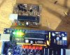
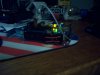
001: General picture.
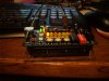
002: Voltage regulation coated in hot glue to prevent something.
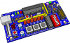
003: Fuzzy front angle picture
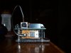
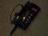
004: Junebug plugged in and working :)

Comments? Questions?
 

Attachments

  • Junebug3D.png
    Junebug3D.png
    275.2 KB · Views: 355
  • junebug 001.jpg
    junebug 001.jpg
    542 KB · Views: 391
  • junebug 002.jpg
    junebug 002.jpg
    379.5 KB · Views: 275
  • junebug 003.jpg
    junebug 003.jpg
    567.3 KB · Views: 183
  • junebug 004.jpg
    junebug 004.jpg
    450.9 KB · Views: 270
AAAAAA!!! Krumlink's gonna beat me to it! Can't get enough free time to play when I'm not unemployed. Been busy building this fancy machinery:

**broken link removed**

**broken link removed**

**broken link removed**

Nice, huh? I did plumbing, heating, gas, vent and electrical. But it's not a proper robot. Can't move around. :p And the microcontroller isn't programmable on this one.
 
Let me guess what that is, a computer :p

Nice plumbing, heating gas vent etc. Its all neat and organized.
 
Let me guess what that is, a computer :p

Nice plumbing, heating gas vent etc. Its all neat and organized.
A computerized boiler. It's the el-cheapo version of Viessmann's flagship Vitodens boilers, so very simple controller and no networked controls. Has just one knob for control and a smallish LCD. They get a lot of functions out of that one knob though. Smart interface.

So. What kind of motor controller, motors, wheels, sensors, etc. do you have planned? Or maybe you haven't thought that far ahead yet? :p
 
I short them out and the rest of the junebug is powered. But a wire is going to look tacky, so I solder and glue on a shorting switch.
Aziz! Light!

How about some nice, well lit and non-blurry macros of the mod. Your camera must have a macro mode, right? Get that thing out into some daylight and take some major closeup pics. Please? :D
 
This is an idea that only sounds good. The Junebug is a nice board and useful in many ways. But it has too few IO lines to be a good robot controller. The target boards I sent you for Walter are both much better suited for controlling a robot. Also I have the prototype for a little programmer board that we can attach to our robots. I have to reboot my computer to get the camera working so I will have to put the image of that in the next post.

We can layout and etch any PCB we want. Please use the Junebugs for their intended purpose: program, debug, UART tool. Logic Analyzer, and IO tool. Please do not mod them!

It is time you STOP thinking about hardware for a while and get with the programming. Follow the two tutorials to the letter to ensure you know where all the needed information comes from. I know they move slow but that is the point. Then work your way through my two articles in JPUG #1. They move much faster and you will have questions.
 
Last edited:
Are those 'Screwit' connectors on the wires?, where you twist the wires together and screw a plastic 'nut' over them?.

They have been illegal in the UK for decades! :D
 
This is the prototype next to a Junebug. I cut off the pins on the 18F2550's ICSP connector because it was too hard to get the chip out. The target connector is a single row of pins. I started it prior to getting Junebugs which are the way to go.

Or you could buy a real PICkit2 and mount it on the robot.
 

Attachments

  • JJ.jpg
    JJ.jpg
    84.5 KB · Views: 237
Last edited:
Are those 'Screwit' connectors on the wires?, where you twist the wires together and screw a plastic 'nut' over them?.

They have been illegal in the UK for decades! :D
You mean **broken link removed**? Or they're also called wire nuts. Totally legal here. They're very safe and secure if done right (wires twisted so they won't come apart even without the Marrette, and tightened tight so they won't come off without a fight). You aren't allowed to use them exposed like that on mains voltage - they have to be in a grounded junction box for that. All the exposed ones there are 24VAC control lines. Unlikely to kill you unless you're standing in the wet and barefoot or get em across the heart with wet hands (and even then probably not), but they can sure give you good sting. Anyway, customers are generally terrified of wiring. :D
 
Last edited:
This is an idea that only sounds good.
It's a ridiculous idea, but a fun challenge. :p See how far we can push the Junebug.

The Junebug is a nice board and useful in many ways. But it has too few IO lines to be a good robot controller.
Agree totally. But it can be fun to work (play) within tight constraints. Makes for good ingenuity.
 
They were banned here back in the 60's or 70's, obviously low voltage use isn't a problem - but it's horrifying to see them still used in 'This Old House' :D
There's another thing to consider too. Here in North America we use 110VAC for household mains. You crazies :p in the UK run 220VAC for mains. Here, 220 is reserved (in residential) only for stuff that really needs it, like clothes dryers, stoves and electric water heaters. But Marrettes are routinely used on 220 as well - just bigger ones to go with the heavier gauge wire.
 
Theres plenty of I/O lines! 2 for the motor controller, and the rest as sensor lines. Plenty of lines.
 
Theres plenty of I/O lines! 2 for the motor controller, and the rest as sensor lines. Plenty of lines.
Make that four for typical motor controller. Two enables (feed em a PWM signal) and two directions (control which way to turn the motor). One of each for each motor.

Unless you're thinking of using gear-hacked servos with original electronics for motors...
 
Last edited:
I wasnt thinking, but I dont think I will need PWM lines for this robot/ wont use PWM. 4 motor lines.
 
There's another thing to consider too. Here in North America we use 110VAC for household mains. You crazies :p in the UK run 220VAC for mains. Here, 220 is reserved (in residential) only for stuff that really needs it, like clothes dryers, stoves and electric water heaters. But Marrettes are routinely used on 220 as well - just bigger ones to go with the heavier gauge wire.

Nah!, we don't use wimpy 220V, we use 240V :p

Although it's now nominally 230V across all the EU, but the UK 240V comes within tolerance, as does the 220V continental mains.

The higher voltage means thinner wires and higher available powers, anything requiring more than 13A at 240V is generally hardwired to the mains (like cookers and showers).

Wires are connected using screw blocks, usually inside the fittings - so a ceiling rose for a light would have the required blocks to join all the wiring. Obviously it gives a much more positive and reliable connection been compressed under a screw.
 
Nah!, we don't use wimpy 220V, we use 240V :p
Ah! Shows how much I know about the UK. :p Not a hell of a lot, as it turns out. :D

Wires are connected using screw blocks, usually inside the fittings - so a ceiling rose for a light would have the required blocks to join all the wiring. Obviously it gives a much more positive and reliable connection been compressed under a screw.
At that kind of voltage screw blocks have to be a LOT more secure than wire nuts. The electrical code people are very good. There are good reasons the rules are what they are in different places.
 
Over here outlets and switches have screw terminals but they also have a way to get around using them. They have a small hole that you push a striped wire end into. A sharp blade makes contact with the wire and keeps it from backing out, sort of like a ratchet. They may only be on 15 amp circuit parts. I do not trust them and always use the screws.
 
Over here outlets and switches have screw terminals but they also have a way to get around using them. They have a small hole that you push a striped wire end into. A sharp blade makes contact with the wire and keeps it from backing out, sort of like a ratchet. They may only be on 15 amp circuit parts. I do not trust them and always use the screws.
I've noticed that those holes have disappeared on the newest parts. They may have been made illegal. I don't know - I'm a plumber/gasfitter (with electrical endorsement for heating equipment), so...
 
Status
Not open for further replies.

Latest threads

New Articles From Microcontroller Tips

Back
Top