Continue to Site

Welcome to our site!

Electro Tech is an online community (with over 170,000 members) who enjoy talking about and building electronic circuits, projects and gadgets. To participate you need to register. Registration is free. Click here to register now.

  • Welcome to our site! Electro Tech is an online community (with over 170,000 members) who enjoy talking about and building electronic circuits, projects and gadgets. To participate you need to register. Registration is free. Click here to register now.

JRC NRD 535 Comms receiver: dead (PSU problem)

Status
Not open for further replies.

joekir

New Member
Hi,

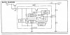
I have a Nrd-535 which was stored for about 5 years in less than optimal conditions....a garage. For those not into radio, the 535 is a fairly good consumer grade receiver. The PSU, which is where the fault lies, is a nice transformer,with secondaries rectified and smoothed and and fed to to an AVR board(marked CBD-1080 AVR in the circuit) which produces 3 regulated voltages, 5V, 9V and 10.8V.

Well, its the 10.8V that's gone...it only reads 1.5V. That's pin 6 on the AVR board. 5V and 9V are fine.

When I first fired it up, some of the pots were scratchy, some of the buttons
inoperative, but it did work...very well in fact.So, I carried on using it and
ordered a can of Cramolin to take care of the pots and buttons.
About a week later, I switched it off, took it to another room and it has not
worked since. The display seems to be lighting up, but very dimly, and every now and again, the whole display will light up on switch on. The audio amp seems to be working OK(uses the 5V supply).

When I looked inside, I was pretty shocked and realised I should never have
switched it on. I'm still cleaning the crud that had somehow accumulated behind the front panel.

Anyway, it looks like my problem is the AVR board ...the 10.8 to be exact at pin 6. The 5 and 9 V are within spec, but pin 6 on the AVR read 1.6V . Also measured at the collector of TR1, same. Pulled TR1 to test and it seems OK. Replaced C4, no change. I did pull all the boards and panel
connections except the main switch BTW. Also cleaned fuse, etc.

Now, I also have an open rectifier diode on the mainboard, but this was done after the problem occurred and anyway, I have a low 10.8 V when I try to run off 12V DC.

I am hoping someone in the group has come across this problem
before, but found nothing in the archive and very little information anywhere.

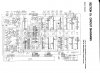
I have posted a circuit diagram of the chassis, which I can crop if necessary and also have access to the service manual pdf.

Thanks,

Joe
 

Attachments

  • chassis.JPG
    chassis.JPG
    1 MB · Views: 1,345
Last edited:
What voltage do you have at the emitter of Tr1?
What voltage do you have between the emitter and base of Tr1?

Does the voltage vary at pin 3 of IC1 when you adjust RV1?
Does the voltage vary at pin 1 of IC1 when you adjust RV1 ?
 
Last edited:
Thanks for the reply:

Emitter V: 16.2V
E-B V: 0.3V, Vfluctuating 20%

Pin 1, IC1: No variation, 15.2V
Pin 3, IC1: Variation, 3.19 to 2.80V

I also changed that IC. Needless to say, after seeing the reputation of these now, I am pretty sick about the way it was stored. Thanks again, Chippie.
 
Well there aint much left to check.....

What about the two diodes? CD1 CD2

What about a short on the 10.8v rail? is the series transistor TR1 getting hot?
 
Yep, that CD2 does look suspect...it gives the same reading in both directions with the diode test. From what I can tell, 2.9-3.1V Zener diode, HZ3B2, so now have to find an equivalent. I'm still not sure that is the problem though.

Because the other voltages are OK, is it *certain* that the problem is on the AVR board? TBH, the motherboard near the rectifier looked much worse...the diodes (now replaced)were discoloured and overheated, there was much more corrosion.

One other thing. while I was checking for a short, I noticed that the supply has an impedance of about 100 Ohms after the AVR board and before about the same. With the AVR in circuit, it's different. When I measure pin 6 to ground, it goes way up to about 2K. Also, Tr1 is not hot, but IC2 is!

When I replace the diode, I will refllow all the joints on the AVR, and if that doesn't work, I'll have to bite the bullet and send it in for repair. Annoying, because it should be a simple fix and no JRC work is cheap.
 
Last edited:
Joe,

I marked up the cct showing the conenctions for CD2...Looks like it is connected to some timer circuitry on the main board?

You should be able to lift off the cathode connection of CD1 to the chip ...See what happens...the supply should return!


Also check if the relay is energised, K1, its also fed from the output of the bridge, does it have any voltage across it?

The timer switch isnt set is it? Look at the bottom of the drawing at the multipole connector J39/P39

I've attached the internal circuit of the M5237l for reference
 

Attachments

  • chassismarkup.JPG
    chassismarkup.JPG
    1 MB · Views: 571
  • M5237l.JPG
    M5237l.JPG
    167.1 KB · Views: 605
Hello Chippie, you were right! Disconnected the cathode and back came the 10.8V! Trouble is, the radio still doesn't switch on. The display is much brighter, but basically the whole display lights up and none of the controls will work. I'm going to try a replacement for CD1 (1N4148 looks ok from the data sheets) and cd2 (BZX79C 3V zener?) and let you know what happens. I will also check out that relay. Thanks for your help so far,
 
Joe, the relay doesnt do much...the cct shows it as an externally available set of c/o contacts...

You need to find out what is pulling the reference voltage low...CD1 and CD2...they go to another connector on the board...Did you try the timer switch?
 
check the diode in parallel with the timer relay for sc..........
 
check the diode in parallel with the timer relay for sc..........


It wouldnt matter if the timer isnt activated......

He needs to check some of the other things suggested, but thanks for chiming in....I was running out of ideas.....:)
 
Hello there Chippie,

Largely thanks to your help, I think I'm getting somewhere. I decided to to take a different approach and strip the chassis right down, which also meant I had much better access to the traces on the MB. BTW, J39 goes to a DPDT switch....the timer is just part of the main switch. Apart from the 5V rail, which goes direct to the front panel, I think for the clock.

Anyway, I noticed that the output of pin 8 ( the diodes) was not getting to J39 and , looking closely, I found a broken trace on the pin 8 output just before J39. I guess the most likely thing is that something caused it to blow, so is there anything I should look out for ? Thanks for the help so far.
 
you said the trace was cracked there, it could have been bad a long time and intermittent, and that would cause it to look burnt, which it seems you meant when you asked what would cause it to burn out there. or if the solder is what's burnt, the solder has been bad a long time, and with current flowing through it caused it to repeatedly heat up, causing it to burn. solder has only 1/6 the conductivity of copper, and so has more of a tendency to self heat than does a copper trace. add to that the heat from a zener diode, and it probably was quite warm there to begin with.

if you have to replace the zener, i recomend you use a 1 watt zener instead of what most likely is a 1/2 watt or 1/4 watt zener. also, you might want to check the soldering in the unit, paying close attention to any areas that generate heat. you might want to also check for dried out electrolytic caps. one of the symptoms of dried out electrolytics is semiconductors that run warmer than normal, since transistors are now amplifying excessive noise currents along with their normal "work". logic ic's are also devices that run hotter with bad caps.
 
Last edited:
Status
Not open for further replies.

Latest threads

New Articles From Microcontroller Tips

Back
Top