Continue to Site

Welcome to our site!

Electro Tech is an online community (with over 170,000 members) who enjoy talking about and building electronic circuits, projects and gadgets. To participate you need to register. Registration is free. Click here to register now.

  • Welcome to our site! Electro Tech is an online community (with over 170,000 members) who enjoy talking about and building electronic circuits, projects and gadgets. To participate you need to register. Registration is free. Click here to register now.

jk flip flop, and how to make it toggle

Status
Not open for further replies.

roelcha

New Member
hi i am quite new to electronics

i have a 5v pulse at about 3000 pulses per minute and i need to halve the speed of this pulse.

i have been told that i can do this with this part
**broken link removed**

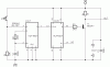
i am hoping that someone can tell me which wires go to which terminal on this jk flip flop

i think that i need

wire 1) 5v+ power constant input

wire 2) 5v+ pulse

wire 3) 5v+ pulse output (half the speed of wire 2)

wire 4) 5v- earth (to make the flip flop work)
the following

i have a 5v+ pulse at between 300 and 3000 pulses per min (which needs to be halved)

and i have a constant 5v+ power source.

i also have a 5v- power supply

what else do i need


please help
 
Power (+5v) goes to the Vcc pin (pin 5);
Ground goes to the GND pin (pin 13);
J & K both go to a logical HIGH which is +5v to set up the toggle function (pins 4 & 16 respectively);
Preset and Clear both go to a logical HIGH to disable them (pins 2 & 3 respectively);
The input is to the CLK (pin 1);
Output is at Q (pin 15).

So, when you're done, your "Wire 1" will connect to pins 2, 3, 4, 5 and 16; "Wire 2" connects to pin 1; "Wire 3" connects to pin 15; and "Wire 4" connects to pin 13.

There are two JK flip flops in a 74LS76 and they have common Vcc and GND pins. Otherwise they are fully independent of each other.
 
hi thanks for your help

i have set this up as you specified, but i have a small problem because in order to make it toggle i seem to need a 5v- pulse, and i have a 5v+ pulse

when i use the + pulse i get no response from the multimeter but when i use the - it toggles.

please help me again
 
Hi Roelcha,

TTL and low power TTL chips normally work with negative logic, while CMOS chips work positive.

Using a HCF4027 you can toggle with a positive going pulse edge.

Here is the schematic.

Q (pin15) goes high on power up, /Q goes low. If you don't want an active output when powering up use /Q (pin14) to toggle.

Boncuk
 

Attachments

  • TOGGLE-01.gif
    TOGGLE-01.gif
    13.5 KB · Views: 2,084
hi

thanks again

i think that this is the chip that boncuk says that i need

**broken link removed**

if this chip will work please let me know

and if it does please help me work out which wires go to which

wire 1) 5v+ power constant input

wire 2) 5v+ pulse

wire 3) 5v+ pulse output (half the speed of wire 2)

wire 4) 5v- earth (to make the flip flop work)
the following

this is what i have, please help me to find out where each wire should go

thanks in advance
 
Status
Not open for further replies.

Latest threads

New Articles From Microcontroller Tips

Back
Top