theo92
New Member
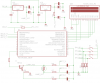
I'm using a PIC uC to generate PWM signal (varying the duty cycle using two up-down push buttons) which powers up a small lamp. Then to measure the voltage and current by ADC of the uC.
I've used a NPN Darlington to switch the lamp. PWM freq. is 36KHz. To meaasure the voltage I've connected the lamp terminals to the ADC inputs using a passive RC low pass filter. the RC filter is made with 100K R and 10nF C. So, the cutoff freq. is nearly 160Hz.
I've connected the emitter of the NPN darlington TIP122 to ground through a 1Ω resistor. And measure the voltage drop using ADC through another RC low pass of same configuration.
The voltage measurement is quite accurate. It increases approx. linearly with increasing duty cycle.
But the problem appears in measuring the current (or the voltage drop through the resistor). The load draws 0mA to 500mA current, so I'd expect 0 to 0.5V voltage drop. Most of the time it shows correct values but sometime it doesn't. Suddenly the voltage drops. I'm showing a log of (logged through UART) voltage vs current(the voltage drop) here in this format {voltage, current}
Can you point out the fault? In RC filter or in ADC config? I think it's not an ADC fault because in most of the time it does measure correct one.
The swordfish code snippet is:
I've used a NPN Darlington to switch the lamp. PWM freq. is 36KHz. To meaasure the voltage I've connected the lamp terminals to the ADC inputs using a passive RC low pass filter. the RC filter is made with 100K R and 10nF C. So, the cutoff freq. is nearly 160Hz.
I've connected the emitter of the NPN darlington TIP122 to ground through a 1Ω resistor. And measure the voltage drop using ADC through another RC low pass of same configuration.
The voltage measurement is quite accurate. It increases approx. linearly with increasing duty cycle.
But the problem appears in measuring the current (or the voltage drop through the resistor). The load draws 0mA to 500mA current, so I'd expect 0 to 0.5V voltage drop. Most of the time it shows correct values but sometime it doesn't. Suddenly the voltage drops. I'm showing a log of (logged through UART) voltage vs current(the voltage drop) here in this format {voltage, current}
{0.000, 0.05371},
{0.087, 0.08300},
{0.190, 0.10253},
{0.322, 0.12207},
{0.439, 0.13671},
{0.551, 0.14648},
{0.639, 0.16113},
{0.805, 0.17089},
{0.805, 0.18554},
{0.922, 0.19531},
{0.996, 0.20507},
{1.088, 0.21972},
{1.166, 0.22949},
{1.245, 0.23925},
{1.328, 0.28808},
{1.425, 0.16601},
{1.484, 0.26855},
{1.533, 0.27832},
{1.669, 0.28320},
{1.723, 0.35644},
{1.791, 0.30273},
{1.914, 0.31250},
{1.992, 0.31738},
{2.070, 0.32714},
Can you point out the fault? In RC filter or in ADC config? I think it's not an ADC fault because in most of the time it does measure correct one.
The swordfish code snippet is:
Code:
Function ReadVoltage() As Float
result = ADC.Read(0) - ADC.Read(1)
result = result * 5 / 1024
End Function

Function ReadCurrent() As Float
result = (ADC.Read(2) + 1)
result = result * 5/1024
End Function
Last edited: