Hi,
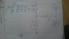
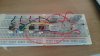
I am building a Full-Bridge Inverter using four IGBT and four drivers for each IGBT. Driver is HCPL-3120, all four drivers are supplied with 15VDC isolated supply. I am switching using M bed micro controller LPC1768 generating two PWM signal working alternately, first signal turns IGBT 1 and 2 on and second turns IGBT 3 and 4. Inverter is supplied with roughly 36V while each driver with 15V. I have uploaded picture of schematic where four IGBT can be seen and one driver although in actual four drivers are used. After testing circuit i am unable to get a sine wave however I have upload snaps of my output. I haven't put any load yet and I am not getting any signal on DC coupled scope, Ac coupled scope is just giving a bit of noise while output voltage is approx. just 2Vp-p. So what I am doing wrong here and what type of output i should be expecting from this circuit .
Any help here is much appreciated.